Expert
- Project scope Vs. Product scope (BA Vs. PM responsibilities)
- Requirements prioritization
- Business rules, their types and context
- Requirements development process
- Stakeholders, RACI Matrix
- Modeling techniques:
- Reviewing requirements - Structured walkthrough, Inspections
- Validating requirements
- Change management – Baselines, Change control Board, scope creep, gold plating
- Tracing requirements, allocating requirements – traceability matrix etc
Project scope Vs. Product scope (BA Vs. PM responsibilities)
Projects are undertaken to deliver a product, service, or result. It will be difficult to achieve your objective if you don’t understand both the project and product scope. In project management, you will find many important concepts vital to complete your project with minimal obstacles. Among these terms and concepts, project scope and product scope stand out.
Project scope depends entirely on the product scope. You must understand the product scope to define the project scope. These are the most important concepts in project management. I have noticed that many professionals incorrectly use these terms synonymously.
I saw a related question posted in a PMP forum a few days ago. Someone was asking for clarification on the differences between project scope and product scope. There were many replies, however some were incomplete, and a few of them were wrong. It seemed like the posters were more concerned with supporting their own opinions.
None of the answers met the asker’s expectations, and honestly, the query was left unanswered.
This is one of the main disadvantages of a forum: you cannot identify the correct answer. It is possible that you may accept any wrong answer that fits with what you already believe. Forums are good for reading lessons learned and other stories, but not good for getting your technical questions clarified.
So, I decided to write a blog post on project scope and product scope.
Before starting the discussion, let’s make sure we understand the terms product, project, and scope.
What is a Product?
The PMBOK Guide sixth edition defines a product as an artifact or a quantifiable that can either be an end item in itself or a component item. These items are also called materials or goods.
In other words, a product is defined as a substance or article produced during a natural, chemical, or manufacturing process. You can characterize a product in many ways, such as by its physical properties and chemical properties.
For example, if a computer is the product, its characteristics are its processor, screen size, memory, and hard disk.
What is a Project?
According to the PMBOK Guide, “A project is a temporary endeavor undertaken to create a unique product, service, or result.”
The first half of the definition says the nature of the project is temporary. This means that once you deliver the output, your project will cease to exist because you’ve achieved the objective.
The second half says that the project produces a deliverable. Projects are undertaken to produce a particular output, which can be tangible or intangible.
What is Scope?
A scope can be defined as the range, detail, or a boundary of a term it is attached to. The word scope is not always standalone; it is used as a suffix or a prefix of another term.
If used with the term product, it means the details of the product, or when used with project, then it means the details of the project.
According to the PMBOK Guide, the scope is the sum of the products, services, and results to be provided as a project.
Product Scope
In short, product scope is about the product details; what the product will look like, how will it work, its features, and more.
According to the PMBOK Guide, sixth edition, product scope is the features and functions that characterize a product, service or result.
For example, if the product is a bridge, the product scope might be its length, width, and load strength. If the product is a cell phone, its product scope will be its screen size, battery backup, processor speed, camera type, and memory.
However, for services, the product scope will give you details on the tasks and responsibilities of the person who will deliver.
In the case of a result, the product scope can be the information required from the result.
How to Determine the Product Scope
Most of the time, the product scope is defined by the people who have higher levels of business expertise. Usually, a business analyst defines the product scope, and although the project manager can be consulted, their role is limited.
The business analyst will meet with every stakeholder to understand their expectations and requirements regarding the final product. Once these are finalized, the analyst will get them signed by stakeholders and then process them for approval.
Make sure that none of the requirements are left out during this process, as adding more towards the end of the project can be costly. A slight change in the product scope can cost you a lot more money than an initial change in the project scope statement. The product scope should be well defined because the project scope is defined according to the product scope.
The product scope is what binds you and your organization to the user who will use the product. You should make every effort to get these specifications exact and complete.
However, if you have a contract to deliver the product to the client, you will find the product scope attached to the contract document.
Project Scope
The project scope defines the requirements of the product and the work required to create it. This also defines what is inside and outside of the scope, which helps you avoid scope creep.
According to the PMBOK Guide, sixth edition, project scope is the work performed to deliver a product, service, or result with the specified features and functions.
The project scope statement explains the expected result and along with the constraints and assumptions. This helps in achieving the product scope. Project scope is also known as scope statement or statement of work.
If you are given a project to construct a bridge, the project scope will provide insight into how to build the bridge. It gives you all the required information. In this case, the project scope defines what exactly you need to construct the bridge. Nothing more.
How to Determine the Project Scope
The project manager defines the project scope, which depends on many factors.
For example, if you receive a firm fixed price contract, the client will give you a well-defined product description, which helps you in developing the project scope statement. In this case, you won’t have to worry too much about the project scope.
However, this isn’t always the case. Let’s consider another case.
Your organization initiates a project, and you are the project manager.
In this case, you may have to build the project scope statement from scratch. You contact the concerned stakeholders to collect the requirements and compile them, and then you get them approved by management.
Likewise, there might be several factors that determine the project scope, such as the client asking you to do everything on their behalf.
A well-written scope statement makes the life of a project manager much more comfortable, and the project will be completed with fewer obstacles. Project scope is an agreement between you and the client or your organization.
Project scope binds you and your project team to your organization; therefore, it should be very lucid and detailed. This document must completed at an early stage of the project. An effective scope statement is necessary to guide a project to successful completion.
Determining the project scope is the first step in establishing the project’s schedule, budget, and resource allocation. Project management plans are made after the project scope is defined.
I hope that now you understand product scope and project scope.
Now it is time to explain these concepts to you with our trademark school building example.
A Real World Example of Project Scope and Product Scope
You get a project to construct a school building. The client gives you their requirements, such as the size of the building, number of rooms, details of the playground, number of toilets, and paint color.
You start working on the project. You estimate the budget, develop the plan, and create a schedule.
After developing and approving the plan, you gather the team and move on to the execution phase. You bring workers to the site and start construction. You complete the school building and then verify with the client whether it is as per their requirements.
Once the client is satisfied, you hand the school building over to them, get the final payment, and the project is closed.
There are two parts to the above example.
In the first part, the client asks you to make a school building and gives you their requirements for it. The school building is the “product,” and the requirements are the “scope.” Therefore, the client gave you is the “product scope.”
In the second part, you construct the school building within the specified time and budget, meeting all the client’s requirements. Lastly, you deliver the product. In this part, the work you have done to construct the school building is the “project scope.”
How Product Scope and Project Scope are Monitored and Controlled
The most important tool to monitor the product scope is the requirement traceability matrix. This ensures that all features of the project are produced, thoroughly analyzed, reviewed, and approved throughout the project life cycle.
This also helps manage change in the product along with the configuration management plan.
Project scope is monitored and controlled using variance analysis.
The Difference Between Project Scope and Product Scope
These are a few differences between project scope and product scope:
- Project scope is the work that delivers the product while the product scope is the sum of all features, functions, and characteristics of the product.
- Product scope is oriented towards the “what” (functional requirements), while project scope is oriented towards the “how” (work related).
- Product scope is defined by the business analyst, though the project manager may have a role. The project scope is totally defined by the project manager.
- An example of project scope is constructing a bridge, while its product scope might be its technical specifications such as length, width, and the amount of load it has to withstand.
Summary
Product scope and project scope are covered in the scope management knowledge area in the PMBOK Guide. The product scope is the end result of the project and project scope is how you are going to achieve it. The project is defined according to the product scope. These are fundamental terms, and you must understand them. To complete the project, you must achieve these two scopes successfully. Product scope is the characteristics of the product, and the project scope includes all the work you will do to make the product.
Project scope is discussed in depth while product scope is covered briefly as it is not in the scope of the PMP Certification Exam. You will see many questions on your test from this topic, so understand these concepts well.
Requirements prioritization
When customer expectations are high and timelines are short, you need to make sure the product delivers the most valuable functionality as early as possible. Prioritization is a way to deal with competing demands for limited resources. Establishing the relative priority of each capability lets you plan construction to provide the highest value at the lowest cost. Prioritization is critical for timeboxed or incremental development with tight, immovable release schedules. In the Extreme Programming methodology, customers select which user stories they'd like implemented in each two- to three-week incremental release, and the developers estimate how many of these stories they can fit into each increment.
A project manager must balance the desired project scope against the constraints of schedule, budget, staff, and quality goals. One way to accomplish this is to drop—or to defer to a later release—low-priority requirements when new, more vital requirements are accepted or when other project conditions change. If the customers don't distinguish their requirements by importance and urgency, project managers must make these decisions on their own. Not surprisingly, customers might not agree with a project manager's priorities; therefore, customers must indicate which requirements are needed initially and which can wait. Establish priorities early in the project, when you have more options available for achieving a successful project outcome, and revisit them periodically.
It's difficult enough to get any one customer to decide which of his requirements are top priority. Achieving consensus among multiple customers with diverse expectations is even harder. People naturally have their own interests at heart and aren't eager to compromise their needs for someone else's benefit. However, contributing to requirements prioritization is one of the customer's responsibilities in the customer-development partnership, as was discussed in Chapter 2, "Requirements from the Customer's Perspective." More than simply defining the sequence of requirements implementation, discussing priorities helps to clarify the customers' expectations.
Customers and developers both should provide input to requirements prioritization. Customers place a high priority on those functions that provide the greatest business or usability benefit. However, once a developer points out the cost, difficulty, technical risk, or trade-offs associated with a specific requirement, the customers might conclude that it isn't as essential as they initially believed. The developer might also decide to implement certain lower priority functions early on because of their impact on the system's architecture.
A common prioritization approach groups requirements into three categories. No matter how you label them, if you're using three categories they boil down to high, medium, and low priority. Such prioritization scales are subjective and imprecise. The stakeholders must agree on what each level means in the scale they use.
One way to assess priority is to consider the two dimensions of importance and urgency (Covey 1989). Every requirement can be considered as being either important or not important and as being either urgent or not urgent. These alternatives yield four possible combinations, which we can use to define a priority scale:
High priority requirements are both important (the user needs the capability) and urgent (the user needs it in the next release). Contractual or legal obligations might dictate that the requirement must be included, or there might be compelling business reasons to implement it promptly.
Medium priority requirements are important (the user needs the capability) but not urgent (they can wait for a later release).
Low priority requirements are not important (the user can live without the capability if necessary) and not urgent (the user can wait, perhaps forever).
Requirements in the fourth quadrant appear to be urgent but they really aren't important. Don't waste your time working on these. They don't add sufficient value to the product.
Requirements Prioritization Based on Importance and Urgency
| Important | Not Important | |
|---|---|---|
| Urgent | High Priority | Don't do these! |
| Not Urgent | Medium Priority | Low Priority |
Include the priority of each requirement in the use-case descriptions, the SRS, or the requirements database. Establish a convention so that the reader knows whether the priority assigned to a high-level requirement is inherited by all its subordinate requirements or whether every individual functional requirement is to have its own priority attribute.
Even a medium-sized project can have hundreds of functional requirements, too many to classify analytically and consistently. To keep it manageable, choose an appropriate level of abstraction for the prioritization—features, use cases, or functional requirements. Within a use case, some alternative courses could have a higher priority than others. You might decide to do an initial prioritization at the feature level and then to prioritize the functional requirements within certain features separately. This will help you to distinguish the core functionality from refinements to schedule for later releases. Document even the low-priority requirements. Their priority might change later, and knowing about them now will help the developers to plan for future enhancements.
On a small project the stakeholders can agree on requirement priorities informally. Large or contentious projects demand a more structured approach, which removes some of the emotion, politics, and guesswork from the process. Several analytical and mathematical techniques have been proposed to assist with requirements prioritization. These methods involve estimating the relative value and relative cost of each requirement. The highest priority requirements are those that provide the largest fraction of the total product value at the smallest fraction of the total cost (Karlsson and Ryan 1997; Jung 1998). Subjectively estimating the cost and value by pairwise comparisons of all the requirements is impractical for more than a couple dozen requirements.
Another alternative is Quality Function Deployment (QFD), a comprehensive method for relating customer value to proposed product features (Zultner 1993; Cohen 1995). A third approach, borrowed from Total Quality Management (TQM), rates each requirement against several weighted project success criteria and computes a score to rank the priority of the requirements. However, few software organizations seem to be willing to undertake the rigor of QFD or TQM.
Apply this prioritization scheme to discretionary requirements, those that aren't top priority. You wouldn't include in this analysis items that implement the product's core business functions, items that you view as key product differentiators, or items that are required for compliance with government regulations. Unless there's a chance that those capabilities could shift to lower priority if conditions change, you're going to incorporate them into the product promptly. Once you've identified those features that absolutely must be included for the product to be releasable, use the model in Table 14-2 to scale the relative priorities of the remaining capabilities. The typical participants in the prioritization process include:
- The project manager, who leads the process, arbitrates conflicts, and adjusts input from the other participants if necessary
- Customer representatives, such as product champions or marketing staff, who supply the benefit and penalty ratings
- Development representatives, such as team technical leads, who provide the cost and risk ratings
Business rules, their types and context
According to the Business Rules Group (1993), "A business rule is a statement that defines or constrains some aspect of the business. It is intended to assert business structure or to control or influence the behavior of the business." Whole methodologies have been developed based on the discovery and documentation of business rules and their implementation in automated business rules systems (Ross 1997; von Halle 2002). Unless you're building a system that is heavily business-rule driven, you don't need an elaborate methodology. Simply identify and document the rules that pertain to your system and link them to specific functional requirements.
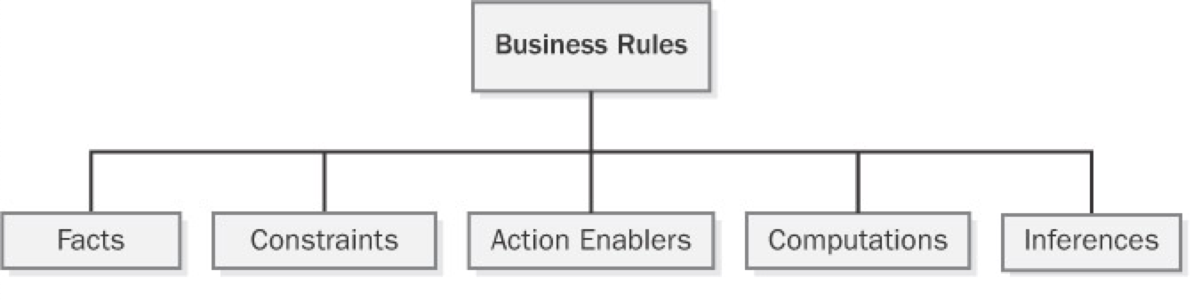
Many different taxonomies (classification schemes) have been proposed for organizing business rules (Ross 2001; Morgan 2002; von Halle 2002). The simple scheme shown in Figure 9-1, with five types of business rules, will work for most situations. A sixth category is terms, defined words, phrases, and abbreviations that are important to the business. A glossary is a convenient place to define terms. Recording the business rules in a consistent way so that they add value to your software development efforts is more important than having heated arguments about how to classify each one. Let's look at the different kinds of business rules you might encounter.
Facts
Facts are simply statements that are true about the business. Often facts describe associations or relationships between important business terms. Facts are also called invariants—immutable truths about data entities and their attributes. Other business rules might refer to certain facts, but facts themselves don't usually translate directly into software functional requirements. Facts about data entities that are important to the system might appear in data models that the analyst or database designer creates. (See Chapter 11, "A Picture Is Worth 1024 Words," for more information about data modeling.) Examples of facts are:
- Every chemical container has a unique bar code identifier.
- Every order must have a shipping charge.
- Each line item in an order represents a specific combination of chemical, grade, container size, and number of containers.
- Nonrefundable tickets incur a fee when the purchaser changes the itinerary.
- Sales tax is not computed on shipping charges.
Constraints
Constraints restrict the actions that the system or its users may perform. Some words and phrases that suggest someone is describing a constraint business rule are must, must not, may not, and only. Examples of constraints are:
- A borrower who is less than 18 years old must have a parent or a legal guardian as cosigner on the loan.
- A library patron may place up to 10 items on hold.
- A user may request a chemical on the Level 1 hazard list only if he has had hazardous-chemical training within the past 12 months.
- All software applications must comply with government regulations for usage by visually impaired persons.
- Correspondence may not display more than four digits of the policyholder's Social Security number.
- Commercial airline flight crews must receive at least eight hours of continuous rest in every 24-hour period.
Action Enablers
A rule that triggers some activity under specific conditions is an action enabler. A person could perform the activity in a manual process. Alternatively, the rule might lead to specifying some software functionality that makes an application exhibit the correct behavior when the specified conditions are true. The conditions that lead to the action could be complex combinations of true and false values for multiple individual conditions. A decision table such as that shown in Chapter 11 provides a concise way to document action-enabling business rules that involve extensive logic. A statement in the form If <some condition is true or some event takes place>, then <something happens> is a clue that someone is describing an action enabler. Following are some examples of action-enabling business rules:
- If the chemical stockroom has containers of a requested chemical in stock, then offer existing containers to the requester.
- If the expiration date for a chemical container has been reached, then notify the person who currently possesses that container.
- On the last day of a calendar quarter, generate the mandated OSHA and EPA reports on chemical handling and disposal for that quarter.
- If the customer ordered a book by an author who has written multiple books, then offer the author's other books to the customer before accepting the order.
Inferences
Sometimes called inferred knowledge, an inference is a rule that establishes some new knowledge based on the truth of certain conditions. An inference creates a new fact from other facts or from computations. Inferences are often written in the "if/then" pattern also found in action-enabling business rules, but the "then" clause of an inference implies a fact or a piece of information, not an action to be taken. Some examples of inferences are:
- If a payment is not received within 30 calendar days of the date it is due, then the account is delinquent.
- If the vendor cannot ship an ordered item within five days of receiving the order, then the item is back-ordered.
- A container of a chemical that can form explosive decomposition products is considered expired one year after its manufacture date.
- Chemicals with an LD50 toxicity lower than 5 mg/kg in mice are considered hazardous.
Computations
Computers compute, so one class of business rules defines computations that are performed using specific mathematical formulas or algorithms. Many computations follow rules that are external to the enterprise, such as income tax withholding formulas. Whereas action-enabling business rules lead to specific software functional requirements to enforce them, computational rules can normally serve as software requirements as they are stated. Following are some examples of computational business rules in text form; alternatively, you could represent these in some symbolic form, such as a mathematical expression. Presenting such rules in the form of a table, as Table 9-1 does, is clearer than writing a long list of complex natural language rule statements.
- The unit price is reduced by 10% for orders of 6 to 10 units, by 20% for orders of 11 to 20 units, and by 35% for orders of more than 20 units.
- The domestic ground shipping charge for an order that weighs more than 2 pounds is $4.75 plus 12 cents per ounce or fraction thereof.
- The commission for securities trades completed on line is $12 per trade of 1 through 5000 shares. The commission for trades conducted through an account officer is $45 per trade of 1 through 5000 shares. Commissions on trades of greater than 5000 shares are one-half of these commissions.
- The total price for an order is computed as the sum of the price of the items ordered, less any volume discounts, plus state and county sales tax for the location to which the order is being shipped, plus the shipping charge, plus an optional insurance charge.
Documenting Business Rules
Because business rules can influence multiple applications, organizations should manage their business rules as enterprise-level—not project-level—assets. A simple business rules catalog will suffice initially. Large organizations or those whose business operations and information systems are heavily business-rule driven should establish a database of business rules. Commercial rule-management tools become valuable if your rules catalog outgrows a word processor or spreadsheet solution or if you want to automate aspects of implementing the rules in your applications. As you identify new rules while working on an application, add them to your catalog rather than embedding them in the documentation for that specific application or—worse—only in its code. Rules related to safety, security, finance, or regulatory compliance pose the highest risk if they are not managed and enforced appropriately.
Sample Businness Rules Catalog
| ID | Rule Definition | Type of Rule | Static or Dynamic | Source |
|---|---|---|---|---|
| ORDER-15 | A user may request a chemical on the Level 1 hazard list only if he has had hazardous-chemical training within the past 12 months. | Constraint | Static | Corporate policy |
| DISC-13 | An order discount is calculated based on the size of the current order, as defined in Table 9-1. | Computation | Dynamic | Corporate policy |
Business Rules and Requirements
Simply asking users "What are your business rules?" doesn't get you very far, just as asking "What do you want?" doesn't help much when eliciting user requirements. Depending on the application, sometimes you invent business rules as you go along and sometimes you discover them during requirements discussions. Often the project stakeholders already know about business rules that will influence the application, and the development team must work within the boundaries that the rules define. Barbara von Halle (2002) describes a comprehensive process for discovering business rules.
During user requirements elicitation workshops, the analyst can ask questions to probe around the rationale for the requirements and constraints that users present. These discussions frequently surface business rules as the underlying rationale. The analyst can harvest business rules during elicitation workshops that also define other requirements artifacts and models (Gottesdiener 2002). Image shows several potential origins of rules (and, in some cases, of use cases and functional requirements). The figure also suggests the types of questions the analyst can ask when workshop participants are discussing various issues and objects. The analyst should document the business rules that come out of these elicitation discussions and ask the right people to confirm their correctness and to supply any missing information.
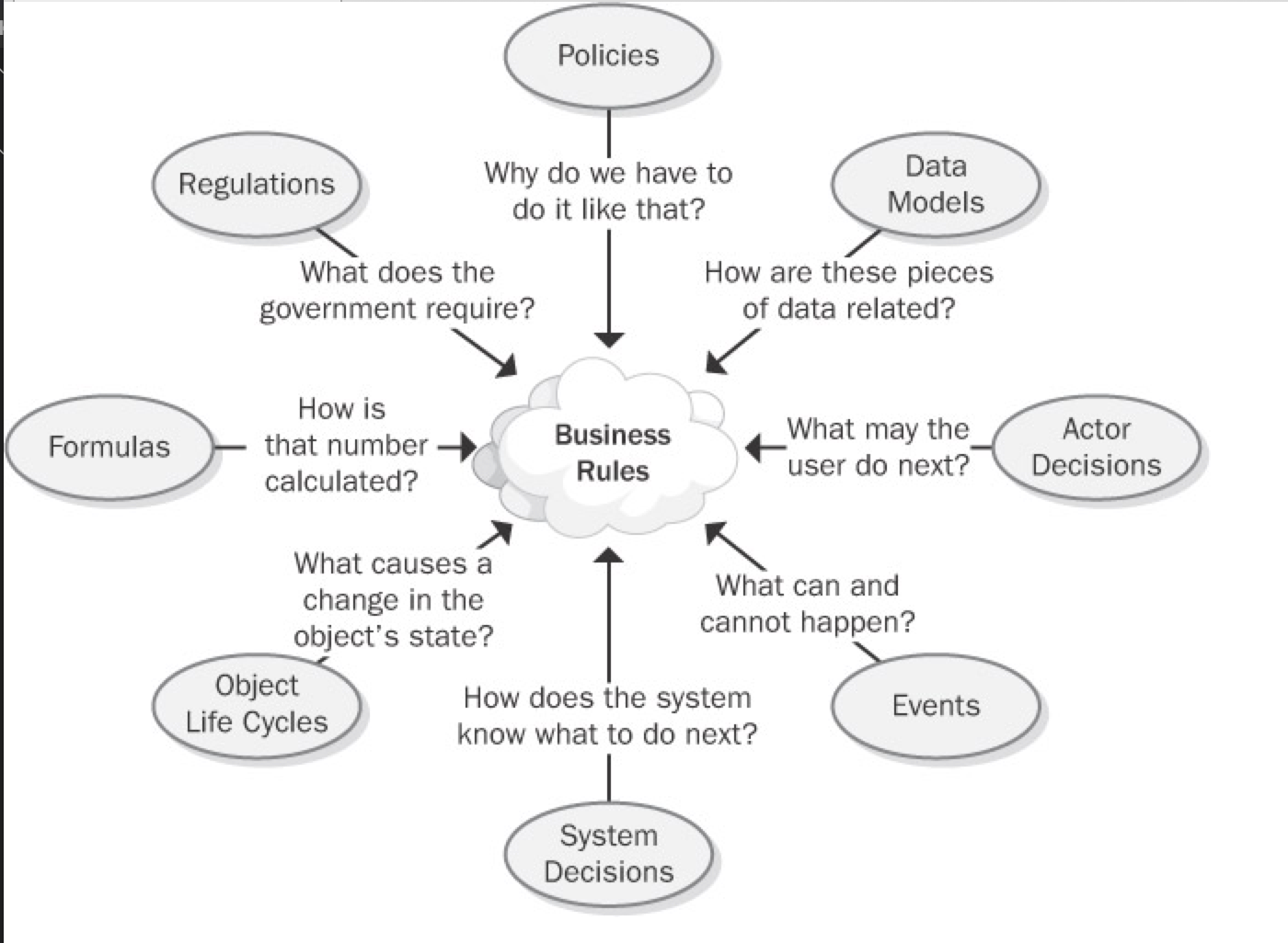
Figure 9-2: Discovering business rules by asking questions from different perspectives.
After identifying and documenting business rules, determine which ones must be implemented in the software. Some rules will lead to use cases and hence to functional requirements that enforce the rule. Consider the following three rules:
- Rule #1 (action enabler) "If the expiration date for a chemical container has been reached, then notify the person who currently possesses that container."
- Rule #2 (inference) "A container of a chemical that can form explosive decomposition products is considered expired one year after its manufacture date."
- Rule #3 (fact) "Ethers can spontaneously form explosive peroxides."
These rules serve as the origin for a use case called "Notify Chemical Owner of Expiration." One functional requirement for that use case is "The system shall e-mail a notification to the current owner of a chemical container on the date the container expires."
You can define the links between a functional requirement and its parent business rules in the following two ways:
- Use a requirement attribute called "Origin" and indicate the rules as the origin of the functional requirement. (See Chapter 18, "Requirements Management Principles and Practices.")
- Define traceability links between a functional requirement and the pertinent business rules in the requirements traceability matrix. (See Chapter 20, "Links in the Requirements Chain.")
Data referential integrity rules frequently are implemented in the form of database triggers or stored procedures. Such rules describe the data updates, insertions, and deletions that the system must perform because of relationships between data entities (von Halle 2002). For example, the system must delete all undelivered line items in an order if the customer cancels the order.
Sometimes business rules and their corresponding functional requirements look much alike. However, the rules are external statements of policy that must be enforced in software, thereby driving system functionality. Every analyst must decide which existing rules pertain to his application, which ones must be enforced in the software, and how to enforce them.
Recall the constraint rule from the Chemical Tracking System requiring that training records be current before a user can request a hazardous chemical. The analyst would derive different functional requirements to comply with this rule, depending on whether the training records database is available on line. If it is, the system can simply look up the user's training record and decide whether to accept or reject the request. If the records aren't available on-line, the system might store the chemical request temporarily and send e-mail to the training coordinator, who in turn could either approve or reject the request. The rule is the same in either situation, but the software functional requirements—the actions to take when the business rule is encountered during execution—vary depending on the system's environment.
To prevent redundancy, don't duplicate rules from your business rules catalog in the SRS. Instead, the SRS should refer back to specific rules as the source of, say, algorithms for income tax withholding. This approach provides several advantages:
- It obviates the need to change both the business rule and the corresponding functional requirements if the rule changes.
- It keeps the SRS current with rule changes because the SRS simply refers to the master copy of the rule.
- It facilitates reusing the same rule in several places in the SRS and across multiple projects without risking an inconsistency, because the rules are not buried in the documentation for any single application.
A developer reading the SRS will need to follow the cross-reference link to access the rule details. This is the trade-off that results when you elect not to duplicate information. There's another risk of keeping the rules separate from the functional requirements: Rules that make sense in isolation might not be so sensible when viewed in an operational context with other requirements. As with so many aspects of requirements engineering, there is no simple, perfect solution to managing business rules that works in all situations.
Organizations that do a masterful job of managing their business rules often don't publicly share their experiences. They view their use of business rules to guide their software portfolio management as providing a competitive advantage over organizations that deal with their rules more casually. Once you begin actively looking for, recording, and applying business rules, the rationale behind your application development choices will become clearer to all stakeholders.
Requirements development process
Requirements lie at the heart of every well-run software project, supporting the other technical and management activities. Changes that you make in your requirements development and management approaches will affect these other processes, and vice versa.
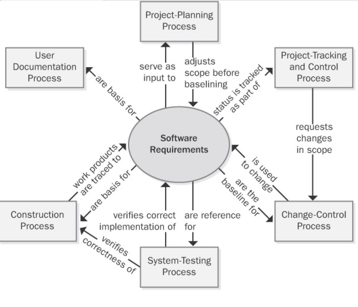
Project planning Requirements are the foundation of the project-planning process. The planners select an appropriate software development life cycle and develop resource and schedule estimates based on the requirements. Project planning might indicate that it's not possible to deliver the entire desired feature set within the available bounds of resources and time. The planning process can lead to reductions in the project scope or to the selection of an incremental or staged-release approach to deliver functionality in phases.
Project tracking and control Project tracking includes monitoring the status of each requirement so that the project manager can see whether construction and verification are proceeding as intended. If not, management might need to request a scope reduction through the change-control process.
Change control After a set of requirements has been baselined, all subsequent changes should be made through a defined change-control process. This process helps ensure that
- The impact of a proposed change is understood.
- The appropriate people make informed decisions to accept changes.
- All people who are affected by a change are made aware of it.
- Resources and commitments are adjusted as needed.
- The requirements documentation is kept current and accurate.
System testing User requirements and functional requirements are essential inputs to system testing. If the expected behavior of the software under various conditions isn't clearly specified, the testers will be hard-pressed to identify defects and to verify that all planned functionality has been implemented as intended.
Construction Although executable software is the ultimate deliverable of a software project, requirements form the foundation for the design and implementation work and they tie together the various construction work products. Use design reviews to ensure that the designs correctly address all of the requirements. Unit testing can determine whether the code satisfies the design specifications and the pertinent requirements. Requirements tracing lets you document the specific software design and code elements that were derived from each requirement.
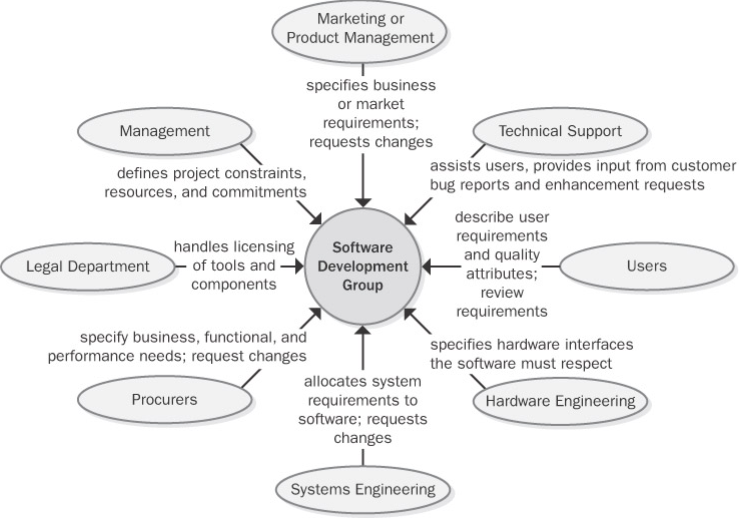
Requirements and Various Stakeholder Groups
Some of the project stakeholders who can interface with a software development group and some of the contributions they make to a project's requirements engineering activities. Explain to your contact people in each functional area the information and contributions you need from them if the product development effort is to succeed. Agree on the form and content of key communication interfaces between development and other functional areas, such as a system requirements specification or a market requirements document. Too often, important project documents are written from the author's point of view without full consideration of the information that the readers of those documents need.
When the software development group changes its requirements processes, the interfaces it presents to other project stakeholder communities also change. People don't like to be forced out of their comfort zone, so expect some resistance to your proposed requirements process changes. Understand the origin of the resistance so that you can both respect it and defuse it. Much resistance comes from fear of the unknown. To reduce the fear, communicate your process improvement rationale and intentions to your counterparts in other areas. Explain the benefits that these other groups will receive from the new process. When seeking collaboration on process improvement, begin from this viewpoint: "Here are the problems we've all experienced. We think that these process changes will help solve those problems. Here's what we plan to do, this is the help we'll need from you, and this is how our work will help us both." Following are some forms of resistance that you might encounter:
- A change-control process might be viewed as a barrier thrown up by development to make it harder to get changes made. In reality, a change-control process is a structure, not a barrier. It permits well-informed people to make good business decisions. The software team is responsible for ensuring that the change process really does work. If new processes don't yield better results, people will find ways to work around them—and they probably should.
- Some developers view writing and reviewing requirements documents as bureaucratic time-wasters that prevent them from doing their "real" work of writing code. If you can explain the high cost of continually rewriting the code while the team tries to figure out what the system should do, developers and managers will better appreciate the need for good requirements.
- If customer-support costs aren't linked to the development process, the development team might not be motivated to change how they work because they don't suffer the consequences of poor product quality.
- If one objective of improved requirements processes is to reduce support costs by creating higher-quality products, the support manager might feel threatened. Who wants to see his empire shrink?
- Busy customers sometimes claim that they don't have time to spend working on the requirements. Remind them of earlier projects that delivered unsatisfactory systems and the high cost of responding to customer input after delivery.
Anytime people are asked to change the way they work, the natural reaction is to ask, "What's in it for me?" However, process changes don't always result in fabulous, immediate benefits for every individual involved. A better question—and one that any process improvement leader must be able to answer convincingly—is, "What's in it for us?" Every process change should offer the prospect of clear benefits to the project team, the development organization, the company, the customer, or the universe. You can often sell these benefits in terms of correcting the known shortcomings of the current ways of working that lead to less than desirable business outcomes.
Fundamentals of Software Process Improvement
You're reading this book presumably because you intend to change some of the current approaches your organization uses for requirements engineering. As you begin your quest for excellent requirements, keep the following four principles of software process improvement in mind (Wiegers 1996a):
Process improvement should be evolutionary, continuous, and cyclical. Don't expect to improve all your processes at once, and accept that you won't get everything right the first time you try to make changes. Instead of aiming for perfection, develop a few improved templates and procedures and get started with implementation. Adjust your approaches as your team gains experience with the new techniques. Sometimes simple and easy changes can lead to substantial gains, so look for the low-hanging fruit.
People and organizations change only when they have an incentive to do so. The strongest incentive for change is pain. I don't mean artificially induced pain, such as management-imposed schedule pressure intended to make developers work harder, but rather the very real pain you've experienced on previous projects. Following are some examples of problems that can provide compelling drivers for changing your requirements processes:
- The project missed deadlines because the requirements were more extensive and complicated than expected.
- Developers worked a lot of overtime because misunderstood or ambiguous requirements were addressed late in development.
- System test effort was wasted because the testers didn't understand what the product was supposed to do.
- The right functionality was present, but users were dissatisfied because of sluggish performance, poor usability, or other quality shortcomings.
- The organization experienced high maintenance costs because customers requested many enhancements that should have been identified during requirements elicitation.
- The development organization acquired a reputation for delivering software that customers don't want.
Process changes should be goal-oriented. Before you begin the journey to superior processes, make sure that you know where you're headed (Potter and Sakry 2002). Do you want to reduce the amount of work that is redone because of requirements problems? Do you want better schedule predictability? Do you want to stop overlooking requirements during implementation? A road map that defines pathways to your business objectives greatly improves your chances of successful process improvement.
Treat your improvement activities as miniprojects. Many improvement initiatives founder because they're poorly planned or because resources never materialize. Include process improvement resources and tasks in your project's overall plans. Perform the planning, tracking, measurement, and reporting that you'd do for any project, scaled down for the size of the improvement project. Write an action plan for each process improvement area you tackle. Track the time the participants spend executing the action plan to check whether you're getting the level of effort you expected and to know how much the improvement work is costing.
The Process Improvement Cycle
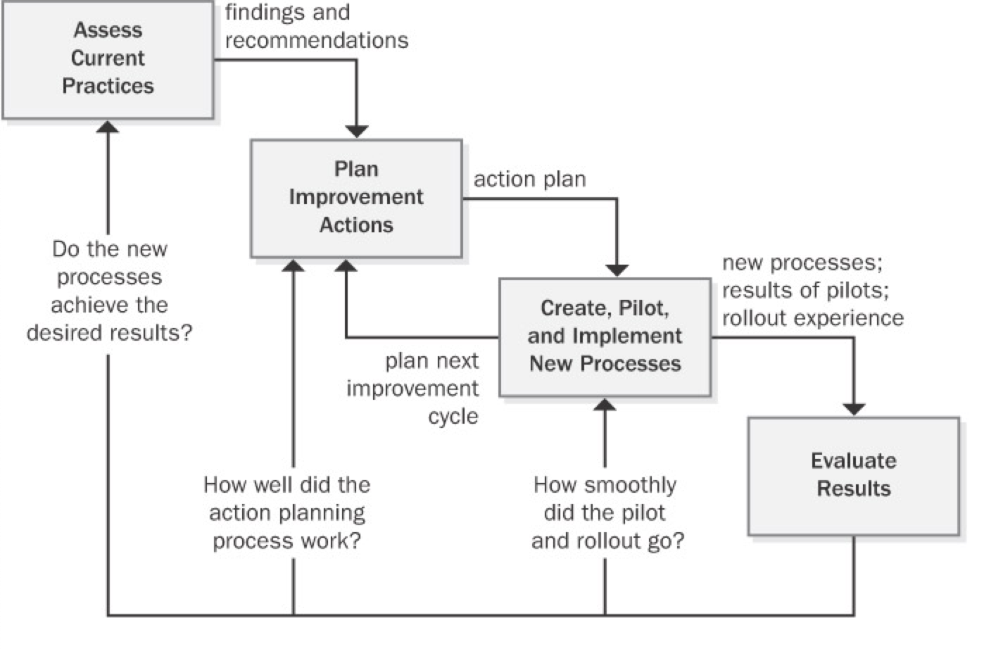
Requirements Engineering Process Assets
High-performance projects have effective processes for all of the requirements engineering components: elicitation, analysis, specification, validation, and management. To facilitate the performance of these processes, every organization needs a collection of process assets (Wiegers 1998c). A process encompasses the actions you take and the deliverables you produce; process assets help the team members perform processes consistently and effectively. These process assets will help those involved in the project understand the steps they should follow and the work products they're expected to create. Process assets include the types of documents described in
| Type | Description |
|---|---|
| checklist | A list that enumerates activities, deliverables, or other items to be noted or verified. Checklists are memory joggers. They help ensure that busy people don't overlook important details. |
| example | A representative of a specific type of work product. Accumulate good examples as your project teams create them. |
| plan | An outline of how an objective will be accomplished and what is needed to accomplish it. |
| policy | A guiding principle that sets a management expectation of behaviors, actions, and deliverables. Processes should enable satisfaction of the policies. |
| procedure | A step-by-step description of the sequence of tasks that accomplishes an activity. Describe the tasks to be performed and identify the project roles that perform them. Don't include tutorial information in a procedure. Guidance documents can support a process or procedure with tutorial information and helpful tips. |
| process description | A documented definition of a set of activities performed for some purpose. A process description might include the process objective, key milestones, participants, communication steps, input and output data, artifacts associated with the process, and ways to tailor the process to different project situations (Caputo 1998). |
| template | A pattern to be used as a guide for producing a complete work product. Templates for key project documents remind you to ask questions that you might otherwise overlook. A well-structured template provides many "slots" for capturing and organizing information. Guidance text embedded in the template will help the document author use it effectively. |
Requirements Development Process Assets
- Requirements development process
- Requirements allocation procedure
- Requirements prioritization procedure
- Vision and scope template
- Use-case template
- Software requirements specification template
- SRS and use-case defect checklists
Requirements Management Process Assets
- Requirements management process
- Change-control process
- Requirements status tracking procedure
- Change control board charter
- Requirements change impact analysis checklist and template
- Requirements traceability procedure
Stakeholders, RACI Matrix
Stakeholders
Each task includes a list of stakeholders who are likely to participate in the execution of that task or who will be affected by it. A stakeholder is an individual or group that a business analyst is likely to interact with directly or indirectly. Any stakeholder can be a source of requirements, assumptions, or constraints.
This list is not intended to be an exhaustive list of all possible stakeholder classifications. Some additional examples of people who fit into each of these generic roles are listed in the definitions below. In most cases there will be multiple stakeholder roles found within each category. Similarly, a single individual may fill more than one role.
For the purpose of the BABOK® Guide, the generic list of stakeholders includes the following roles:
- business analyst
- customer
- domain subject matter expert
- end user
- implementation subject matter
- expert
- operational support
- project manager
- regulator
- sponsor
- supplier
- tester
Business Analyst
The business analyst is inherently a stakeholder in all business analysis activities. The BABOK® Guide presumes that the business analyst is responsible and accountable for the execution of these activities. In some cases the business analyst may also be responsible for performing activities that fall under another stakeholder role.
Customer
A customer uses or may use products or services produced by the enterprise and may have contractual or moral rights that the enterprise is obliged to meet.
Domain Subject Matter Expert
A domain subject matter expert is any individual with in-depth knowledge of a topic relevant to the business need or solution scope. This role is often filled by people who may be end users or people who have in-depth knowledge of the solution such as managers, process owners, legal staff, consultants, and others.
End User
End users are stakeholders who directly interact with the solution. End users can include all participants in a business process, or who use the product or solution.
Implementation Subject Matter Expert
An implementation subject matter expert is any stakeholder who has specialized knowledge regarding the implementation of one or more solution components.
While it is not possible to define a listing of implementation subject matter expert roles that are appropriate for all initiatives, some of the most common roles are: project librarian, change manager, configuration manager, solution architect, developer, database administrator, information architect, usability analyst, trainer, and organizational change consultant.
Operational Support
Operational support is responsible for the day-to-day management and maintenance of a system or product. While it is not possible to define a listing of operational support roles that are appropriate for all initiatives, some of the most common roles are: operations analyst, product analyst, help desk, and release manager.
Project Manager
Project managers are responsible for managing the work required to deliver a solution that meets a business need, and for ensuring that the project's objectives are met while balancing the project factors including scope, budget, schedule, resources, quality, and risk.
While it is not possible to completely define a listing of project management roles that are appropriate for all initiatives, some of the most common roles are: project lead, technical lead, product manager, and team leader.
Regulator
Regulators are responsible for the definition and enforcement of standards. Standards can be imposed on the solution by regulators through legislation, corporate governance standards, audit standards, or standards defined by organizational centers of competency. Alternate roles are government, regulatory bodies, and auditor.
Sponsor
Sponsors are responsible for initiating the effort to define a business need and develop a solution that meets that need. They authorize the work to be performed, and control the budget and scope for the initiative. Alternate roles are executive and project sponsor.
Supplier
A supplier is a stakeholder outside the boundary of a given organization or organizational unit. Suppliers provide products or services to the organization and may have contractual or moral rights and obligations that must be considered. Alternate roles are providers, vendors, and consultants.
Tester
Testers are responsible for determining how to verify that the solution meets the requirements defined by the business analyst, as well as conducting the verification process. Testers also seek to ensure that the solution meets applicable quality standards, and that the risk of defects or failures is understood and minimized. An alternate role is quality assurance analyst.
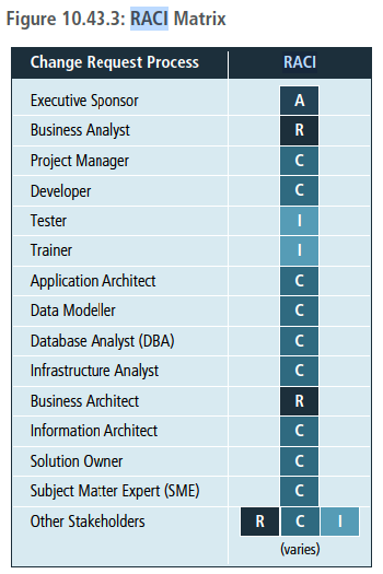
RACI (Responsible, Accountable, Consulted, Informed) matrix
RACI stands for the four types of responsibility that a stakeholder may hold on the initiative: Responsible, Accountable, Consulted, and Informed. When completing a RACI matrix, it is important to ensure that all stakeholders or stakeholder groups have been identified. Further analysis is then conducted to assign the RACI designation in order to specify the level of responsibility expected from each stakeholder and/or group. It is common practice to define each term so that a consistent understanding of the assignment and associated roles are understood by any stakeholders utilizing the RACI matrix.
- Responsible (R): the persons who will be performing the work on the task.
- Accountable (A): the person who is ultimately held accountable for successful completion of the task and is the decision maker. Only one stakeholder receives this assignment.
- Consulted (C): the stakeholder or stakeholder group who will be asked to provide an opinion or information about the task. This assignment is often provided to the subject matter experts (SMEs).
- Informed (I): a stakeholder or stakeholder group that is kept up to date on the task and notified of its outcome. Informed is different from Consulted as with Informed the communication is one-direction (business analyst to stakeholder) and with Consulted the communication is two-way.
Modeling techniques
functional decomposition
Purpose
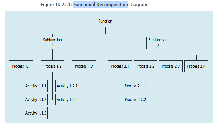
Functional decomposition helps manage complexity and reduce uncertainty by breaking down processes, systems, functional areas, or deliverables into their simpler constituent parts and allowing each part to be analyzed independently.
Description
Functional decomposition approaches the analysis of complex systems and concepts by considering them as a set of collaborating or related functions, effects, and components. This isolation helps reduce the complexity of the analysis. Breaking down larger components into sub-components allows scaling, tracking, and measuring work effort for each of them. It also facilitates evaluation of the success of each sub-component as it relates to other larger or smaller components.
The depth of decomposition may vary depending on the nature of components and objectives. Functional decomposition assumes that sub-components can and do completely describe their parent components. Any sub-component can have only one parent component when developing the functional hierarchy.
The diagram below provides an example of how a function can be broken down to manageable, measurable sub-components.
A wide variety of diagramming techniques can be used to represent functional decomposition, including:
- Tree diagrams: represent hierarchical partitioning of work, activities, or deliverables.
- Nested diagrams: illustrate hierarchical part-to-whole relationships between decomposition results.
- Use Case diagrams: represent decomposition of a higher-level use case.
- Flow diagrams: depict results of a process or function decomposition.
- State Transition diagrams: explain the behaviour of an object inside its composite state.
- Cause-Effect diagrams: elaborate on events, conditions, activities, and effects involved in producing a complex outcome or phenomenon.
- Decision Trees: detail the structure of a complex decision and its potential outcomes.
- Mind Maps: represent information in categories.
- Component diagram: depicts how components are wired together to form larger components and/or software systems.
- Decision Model and Notation: is used to analyze the business logic to ensure that it has inferential and business integrity.
Scenarios and use cases
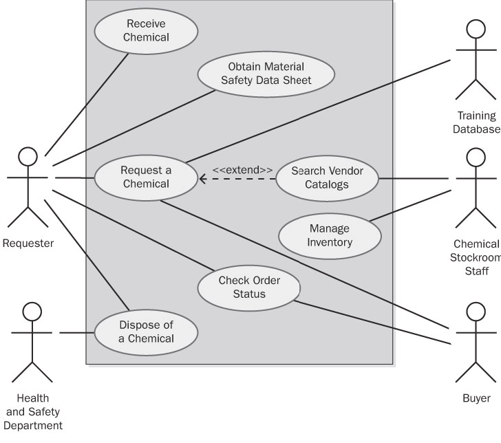
A use case describes a sequence of interactions between a system and an external actor. An actor is a person, another software system, or a hardware device that interacts with the system to achieve a useful goal (Cockburn 2001). Another name for actor is user role, because actors are roles that the members of one or more user classes can perform with respect to the system (Constantine and Lockwood 1999). For example, the Chemical Tracking System's use case called "Request a Chemical" involves an actor named Requester. There is no Chemical Tracking System user class named Requester. Both chemists and members of the chemical stockroom staff may request chemicals, so members of either user class may perform the Requester role.
Use cases emerged from the object-oriented development world. However, projects that follow any development approach can use them because the user doesn't care how the software is built. Use cases are at the center of the widely used Unified Software Development Process (Jacobson, Booch, and Rumbaugh 1999).
Use cases shift the perspective of requirements development to discussing what users need to accomplish, in contrast to the traditional elicitation approach of asking users what they want the system to do. The objective of the use-case approach is to describe all tasks that users will need to perform with the system. The stakeholders ensure that each use case lies within the defined project scope before accepting it into the requirements baseline. In theory, the resulting set of use cases will encompass all the desired system functionality. In practice, you're unlikely to reach complete closure, but use cases will bring you closer than any other elicitation technique I have used.
Use-case diagrams provide a high-level visual representation of the user requirements. Figure 8-1 shows a partial use-case diagram for the Chemical Tracking System, using the UML notation (Booch, Rumbaugh, and Jacobson 1999; Armour and Miller 2001). The box represents the system boundary. Lines from each actor (stick figure) connect to the use cases (ovals) with which the actor interacts. Note the resemblance of this use-case diagram to the context diagram in Figure 5-3. In the use-case diagram, the box separates some top-level internals of the system—the use cases—from the external actors. The context diagram also depicts objects that lie outside the system, but it provides no visibility into the system internals.
Use Cases and Usage Scenarios
A use case is a discrete, stand-alone activity that an actor can perform to achieve some outcome of value. A single use case might encompass a number of similar tasks having a common goal. A use case is therefore a collection of related usage scenarios, and a scenario is a specific instance of a use case. When exploring user requirements, you can start with abstract use cases and develop concrete usage scenarios, or you can generalize from a specific scenario to the broader use case. Later in this chapter we'll see a detailed template for documenting use cases. The essential elements of a use-case description are the following:
- A unique identifier
- A name that succinctly states the user task in the form of "verb + object," such as "Place an Order"
- A short textual description written in natural language
- A list of preconditions that must be satisfied before the use case can begin
- Postconditions that describe the state of the system after the use case is successfully completed
- A numbered list of steps that shows the sequence of dialog steps or interactions between the actor and the system that leads from the preconditions to the postconditions
One scenario is identified as the normal course of events for the use case; it is also called the main course, basic course, normal flow, primary scenario, main success scenario, and happy path. The normal course for the "Request a Chemical" use case is to request a chemical that's available in the chemical stockroom.
Other valid scenarios within the use case are described as alternative courses or secondary scenarios (Schneider and Winters 1998). Alternative courses also result in successful task completion and satisfy the use case's postconditions. However, they represent variations in the specifics of the task or in the dialog sequence used to accomplish the task. The normal course can branch off into an alternative course at some decision point in the dialog sequence and rejoin the normal course later. Although most use cases can be described in simple prose, a flowchart or a UML activity diagram is a useful way to visually represent the logic flow in a complex use case, as shown in Figure 8-2. Flowcharts and activity diagrams show the decision points and conditions that cause a branch from the main course into an alternative course.
sequence diagrams
Purpose
Sequence diagrams are used to model the logic of usage scenarios by showing the information passed between objects in the system through the execution of the scenario.
Description
A sequence diagram shows how processes or objects interact during a scenario. The classes required to execute the scenario and the messages they pass to one another (triggered by steps in the use case) are displayed on the diagram. The sequence diagram shows how objects used in the scenario interact, but not how they are related to one another. Sequence diagrams are also often used to show how user interface components or software components interact.
The diagram represents information in a horizontal and vertical alignment. The objects that send messages to each other are represented as boxes that are aligned at the top of the page from the left to the right, with each object occupying a column of space on the page bordered by a vertical line stretching down to the bottom of the page. The messages that are sent from one object to the next are represented as horizontal arrows. The order of the messages is represented in a top-down and left-to-right sequence beginning with the first message at the top left of the page and subsequent messages occurring to the right and below. Sequence diagrams are sometimes called event diagrams. The standard notation for sequence diagrams is defined as part of the Unified Modelling Language™ (UML®) specification.
State diagrams
All software systems involve a combination of functional behavior, data manipulation, and state changes. Real-time systems and process control applications can exist in one of a limited number of states at any given time. A state change can take place only when well-defined criteria are satisfied, such as receiving a specific input stimulus under certain conditions. An example is a highway intersection that incorporates vehicle sensors, protected turn lanes, and pedestrian crosswalk buttons and signals. Many information systems deal with business objects—sales orders, invoices, inventory items, and the like—with life cycles that involve a series of possible statuses. System elements that involve a set of states and changes between them can be regarded as finite-state machines (Booch, Rumbaugh, Jacobson 1999).
Describing a complex finite-state machine in natural language creates a high probability of overlooking a permitted state change or including a disallowed change. Depending on how the SRS is organized, requirements that pertain to the state machine's behavior might be sprinkled throughout it. This makes it difficult to reach an overall understanding of the system's behavior.
The state-transition diagram provides a concise, complete, and unambiguous representation of a finite-state machine. A related technique is the statechart diagram included in the Unified Modeling Language (UML), which has a somewhat richer set of notations and which models the states an object goes through during its lifetime (Booch, Rumbaugh, Jacobson 1999). The STD contains three types of elements:
- Possible system states, shown as rectangles.
- Allowed state changes or transitions, shown as arrows connecting pairs of rectangles.
- Events or conditions that cause each transition to take place, shown as text labels on each transition arrow. The label might identify both the event and the corresponding system response.
Figure 11-3 illustrates a portion of an STD for a home security system. The STD for a real-time system includes a special state usually called Idle (equivalent to Disarmed in the figure), to which the system returns whenever it isn't doing other processing. In contrast, the STD for an object that passes through a defined life cycle, such as a chemical request, will have one or more termination states, which represent the final status values that an object can have.
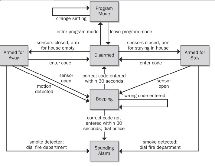
Figure 11-3: Partial state-transition diagram for a home security system.
The STD doesn't show the details of the processing that the system performs; it shows only the possible state changes that result from that processing. An STD helps developers understand the intended behavior of the system. It's a good way to check whether all the required states and transitions have been correctly and completely described in the functional requirements. Testers can derive test cases from the STD that cover all allowed transition paths. Customers can read an STD with just a little coaching about the notation—it's just boxes and arrows.
Recall from Chapter 8 that a primary function of the Chemical Tracking System is to permit actors called Requesters to place requests for chemicals, which can be fulfilled either from the chemical stockroom's inventory or by placing orders to outside vendors. Each request will pass through a series of states between the time it's created and the time it's either fulfilled or canceled (the two termination states). Thus, we can treat the life cycle of a chemical request as a finite-state machine and model it as shown in Figure 11-4.
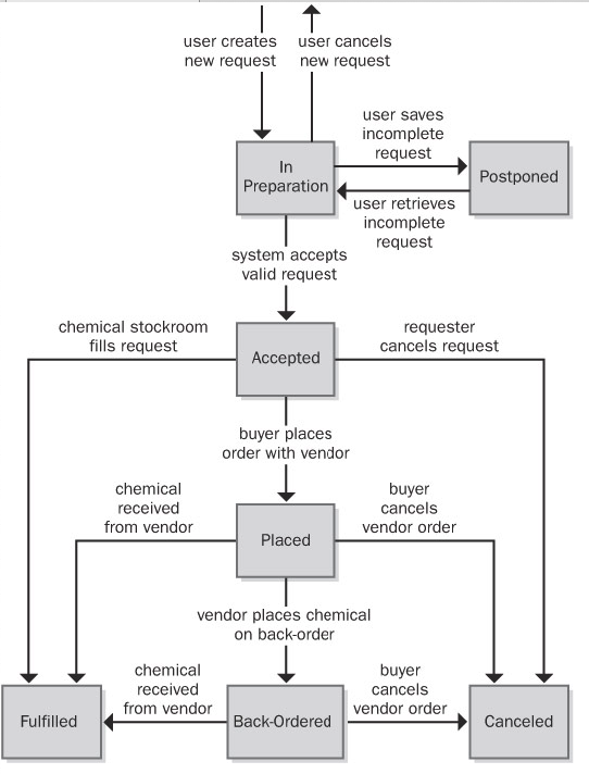
Figure 11-4: State-transition diagram for a chemical request in the Chemical Tracking System.
This STD shows that an individual request can take on one of the following seven possible states:
- In Preparation The Requester is creating a new request, having initiated that function from some other part of the system.
- Postponed The Requester saved a partial request for future completion without either submitting the request to the system or canceling the request operation.
- Accepted The user submitted a completed chemical request and the system accepted it for processing.
- Placed The request must be satisfied by an outside vendor and a buyer has placed an order with the vendor.
- Fulfilled The request has been satisfied, either by delivering a chemical container from the chemical stockroom to the Requester or by receiving a chemical from a vendor.
- Back-Ordered The vendor didn't have the chemical available and notified the buyer that it was back-ordered for future delivery.
- Canceled The Requester canceled an accepted request before it was fulfilled or the buyer canceled a vendor order before it was fulfilled or while it was back-ordered.
Event Response Table
Another way to organize and document user requirements is to identify the external events to which the system must respond. An event is some change or activity that takes place in the user's environment that stimulates a response from the software system (McMenamin and Palmer 1984; Wiley 2000). An event-response table (also called an event table or an event list) lists all such events and the behavior the system is expected to exhibit in reaction to each event. There are several types of system events, as shown in Figure 8-9 and described here:
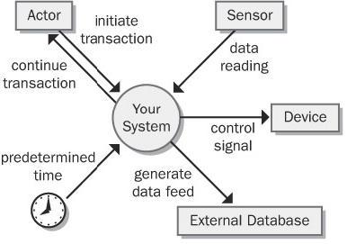
- An action by a human user that stimulates a dialog with the software, as when the user initiates a use case (sometimes called a business event). The event-response sequences correspond to the dialog steps in a use case. Unlike use cases, the event-response table does not describe the user's goal in using the system or state why this event-response sequence provides value to the user.
- A control signal, data reading, or interrupt received from an external hardware device, such as when a switch closes, a voltage changes, or the user moves the mouse.
- A time-triggered event, as when the computer's clock reaches a specified time (say, to launch an automatic data export operation at midnight) or when a preset duration has passed since a previous event (as in a system that logs the temperature read by a sensor every 10 seconds).
Event-response tables are particularly appropriate for real-time control systems. Table 8-1 contains a sample event-response table that partially describes the behavior of an automobile's windshield wipers. Note that the expected response depends not only on the event but also on the state the system is in at the time the event takes place. For instance, events 4 and 5.1 in Table 8-1 result in slightly different behaviors depending on whether the wipers were on at the time the user set the wiper control to the intermittent setting. A response might simply alter some internal system information (events 4 and 7.1 in the table) or it could result in an externally visible result (most other events).
The event-response table records information at the user-requirements level. If the table defines and labels every possible combination of event, state, and response (including exception conditions), the table can also serve as part of the functional requirements for that portion of the system. However, the analyst must supply additional functional and nonfunctional requirements in the SRS. For example, how many cycles per minute does the wiper perform on the slow and fast wipe settings? Do the intermittent wipes operate at the slow or fast speed? Is the intermittent setting continuously variable or does it have discrete settings? What are the minimum and maximum delay times between intermittent wipes? If you stop requirements specification at the user-requirements level, the developer has to track down this sort of information himself. Remember, the goal is to specify the requirements precisely enough that a developer knows what to build.
Decision Tables and Decision Trees
A software system is often governed by complex logic, with various combinations of conditions leading to different system behaviors. For example, if the driver presses the accelerate button on a car's cruise control system and the car is currently cruising, the system increases the car's speed, but if the car isn't cruising, the input is ignored. The SRS needs functional requirements that describe what the system should do under all possible combinations of conditions. However, it's easy to overlook a condition, which results in a missing requirement. These gaps are hard to spot by manually reviewing a textual specification.
Decision tables and decision trees are two alternative techniques for representing what the system should do when complex logic and decisions come into play (Davis 1993). The decision table lists the various values for all the factors that influence the behavior and indicates the expected system action in response to each combination of factors. The factors can be shown either as statements with possible conditions of true and false or as questions with possible answers of yes and no. Of course, you can also use decision tables with factors that can have more than two possible values.
Don't create both a decision table and a decision tree to show the same information; either one will suffice.
Table 11-2 shows a decision table with the logic that governs whether the Chemical Tracking System should accept or reject a request for a new chemical. Four factors influence this decision:
- Whether the user who is creating the request is authorized to do so
- Whether the chemical is available either in the chemical stockroom or from a vendor
- Whether the chemical is on the list of hazardous chemicals that require special training in safe handling
- Whether the user who is creating the request has been trained in handling this type of hazardous chemical
Each of these four factors has two possible conditions, true or false. In principle, this gives rise to 24, or 16, possible true/false combinations, for a potential of 16 distinct functional requirements. In practice, though, many of the combinations lead to the same system response. If the user isn't authorized to request chemicals, then the system won't accept the request, so the other conditions are irrelevant (shown as a dash in a cell in the decision table). The table shows that only five distinct functional requirements arise from the various logic combinations.
Table 11-2: Sample Decision Table for the Chemical Tracking System
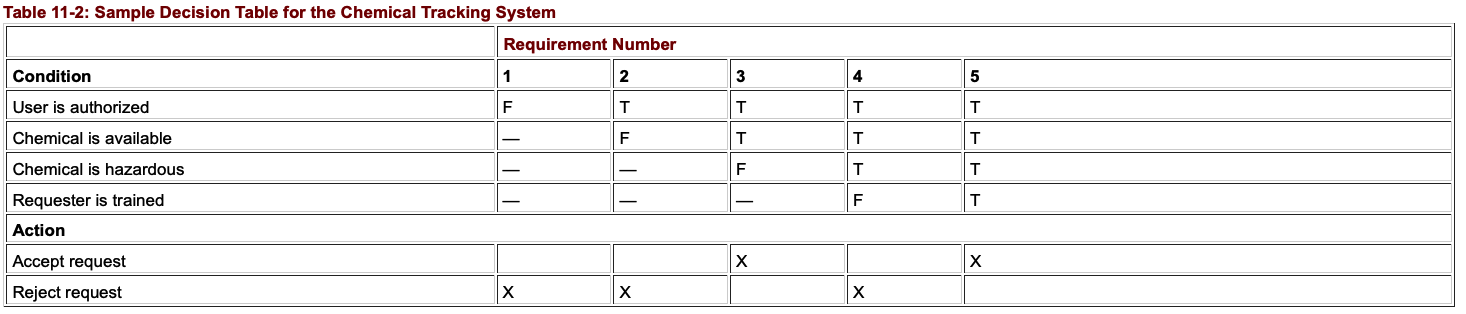
Figure 11-7 shows a decision tree that represents this same logic. The five boxes indicate the five possible outcomes of either accepting or rejecting the chemical request. Both decision tables and decision trees are useful ways to document requirements (or business rules) to avoid overlooking any combinations of conditions. Even a complex decision table or tree is easier to read than a mass of repetitious textual requirements.
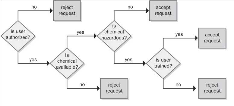
Figure 11-7: Sample decision tree for the Chemical Tracking System.
Dialog Map
A user interface also can be regarded as a finite-state machine. Only one dialog element (such as a menu, workspace, dialog box, line prompt, or touch screen display) is available at any given time for user input. The user can navigate to certain other dialog elements based on the action he takes at the active input location. The number of possible navigation pathways can be large in a complex graphical user interface, but the number is finite and the options usually are known. Therefore, many user interfaces can be modeled with a form of state-transition diagram called a dialog map (Wasserman 1985; Wiegers 1996a). Constantine and Lockwood (1999) describe a similar technique called a navigation map, which includes a richer set of notations for representing different types of interaction elements and context transitions.
The dialog map represents a user interface design at a high level of abstraction. It shows the dialog elements in the system and the navigation links among them, but it doesn't show the detailed screen designs. A dialog map allows you to explore hypothetical user interface concepts based on your understanding of the requirements. Users and developers can study a dialog map to reach a common vision of how the user might interact with the system to perform a task. Dialog maps are also useful for modeling the visual architecture of a Web site. Navigation links that you build into the Web site appear as transitions on the dialog map. Dialog maps are related to system storyboards, which also include a short description of each screen's purpose (Leffingwell and Widrig 2000).
Dialog maps capture the essence of the user–system interactions and task flow without bogging the team down in detailed screen layouts. Users can trace through a dialog map to find missing, incorrect, or unnecessary transitions, and hence missing, incorrect, or unnecessary requirements. The abstract, conceptual dialog map formulated during requirements analysis serves as a guide during detailed user interface design.
Just as in ordinary state-transition diagrams, the dialog map shows each dialog element as a state (rectangle) and each allowed navigation option as a transition (arrow). The condition that triggers a user interface navigation is shown as a text label on the transition arrow. There are several types of trigger conditions:
- A user action, such as pressing a function key or clicking a hyperlink or a dialog box button
- A data value, such as an invalid user input that triggers an error message display
- A system condition, such as detecting that a printer is out of paper
- Some combination of these, such as typing a menu option number and pressing the Enter key
Dialog maps look a bit like flowcharts but they serve a different purpose. A flowchart explicitly shows the processing steps and decision points, but not the user interface displays. In contrast, the dialog map does not show the processing that takes place along the transition lines that connect one dialog element to another. The branching decisions (usually user choices) are hidden behind the display screens shown as rectangles on the dialog map, and the conditions that lead to displaying one screen or another appear in the labels on the transitions. You can think of the dialog map as a sort of negative image of—or a complement to—a flowchart.
To simplify the dialog map, omit global functions such as pressing the F1 key to bring up a help display from every dialog element. The SRS section on user interfaces should specify that this functionality will be available, but showing lots of help-screen boxes on the dialog map clutters the model while adding little value. Similarly, when modeling a Web site, you needn't include standard navigation links that will appear on every page in the site. You can also omit the transitions that reverse the flow of a Web page navigation sequence because the Web browser's Back button handles that navigation.
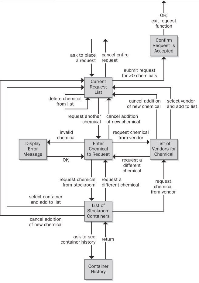
Figure 11-5: Dialog map for the "Request a Chemical" use case from the Chemical Tracking System.
This diagram might look complicated at first, but if you trace through it one line and one box at a time, it's not difficult to understand. The user initiates this use case by asking to place a request for a chemical from some menu in the Chemical Tracking System. In the dialog map, this action brings the user to the box called Current Request List, along the arrow in the upper-left part of the dialog map. That box represents the main workspace for this use case, a list of the chemicals in the user's current request. The arrows leaving that box on the dialog map show all the navigation options—and hence functionality—available to the user in that context:
- Cancel the entire request.
- Submit the request if it contains at least one chemical.
- Add a new chemical to the request list.
- Delete a chemical from the list.
The last operation, deleting a chemical, doesn't involve another dialog element; it simply refreshes the current request list display after the user makes the change.
As you trace through this dialog map, you'll see elements that reflect the rest of the "Request a Chemical" use case:
- One flow path for requesting a chemical from a vendor
- Another path for fulfillment from the chemical stockroom
- An optional path to view the history of a container in the chemical stockroom
- An error message display to handle entry of an invalid chemical identifier or other error conditions that could arise
Some of the transitions on the dialog map allow the user to back out of operations. Users get annoyed if they are forced to complete a task even though they change their minds partway through it. The dialog map lets you enhance usability by designing in those back-out and cancel options at strategic points.
A user who reviews this dialog map might spot a missing requirement. For example, a cautious user might want to confirm the operation that leads to canceling an entire request to avoid inadvertently losing data. It costs less to add this new function at the analysis stage than to build it into a completed product. Because the dialog map represents just the conceptual view of the possible elements involved in the interaction between the user and the system, don't try to pin down all the user interface design details at the requirements stage. Instead, use these models to help the project stakeholders reach a common understanding of the system's intended functionality.
Reviewing requirements - Structured walkthrough, Inspections
Any time someone other than the author of a software work product examines the product for problems, a peer review is taking place. Reviewing requirements documents is a powerful technique for identifying ambiguous or unverifiable requirements, requirements that aren't defined clearly enough for design to begin, and other problems.
Different kinds of peer reviews go by a variety of names (Wiegers 2002a). Informal reviews are useful for educating other people about the product and collecting unstructured feedback. However, they are not systematic, thorough, or performed in a consistent way. Informal review approaches include:
- A peer deskcheck, in which you ask one colleague to look over your work product
- A passaround, in which you invite several colleagues to examine a deliverable concurrently
- A walkthrough, during which the author describes a deliverable and solicits comments on it
In contrast to the ad hoc nature of informal reviews, formal peer reviews follow a well-defined process. A formal review produces a report that identifies the material, the reviewers, and the review team's judgment as to whether the product is acceptable. The principal deliverable is a summary of the defects found and the issues raised. The members of a formal review team share responsibility for the quality of the review, although authors are ultimately responsible for the quality of the products they create (Freedman and Weinberg 1990).
The best-established type of formal peer review is called an inspection (Gilb and Graham 1993; Radice 2002). Inspection of requirements documents is arguably the highest-leverage software quality technique available. Several companies have avoided as much as 10 hours of labor for every hour they invested in inspecting requirements documents and other software deliverables (Grady and Van Slack 1994). A 1000 percent return on investment is not to be sneezed at.
Participants
The participants in an inspection should represent four perspectives (Wiegers 2002a):
- The author of the work product and perhaps peers of the author The analyst who wrote the requirements document provides this perspective.
- The author of any predecessor work product or specification for the item being inspected This might be a system engineer or an architect who can ensure that the SRS properly details the system specification. In the absence of a higher-level specification, the inspection must include customer representatives to ensure that the SRS describes their requirements correctly and completely.
- People who will do work based on the item being inspected For an SRS, you might include a developer, a tester, a project manager, and a user documentation writer. These inspectors will detect different kinds of problems. A tester is most likely to catch an unverifiable requirement; a developer can spot requirements that are technically infeasible.
- People who are responsible for work products that interface with the item being inspected These inspectors will look for problems with the external interface requirements. They can also spot ripple effects, in which changing a requirement in the SRS being inspected affects other systems.
Try to limit the team to six or fewer inspectors. This means that some perspectives won't be represented in every inspection. Large teams easily get bogged down in side discussions, problem solving, and debates over whether something is really an error. This reduces the rate at which they cover the material during the inspection and increases the cost of finding each defect.
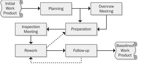
Validating requirements
Purpose
The purpose of Validate Requirements is to ensure that all requirements and designs align to the business requirements and support the delivery of needed value.
Description
Requirements validation is an ongoing process to ensure that stakeholder, solution, and transition requirements align to the business requirements and that the designs satisfy the requirements.
Understanding what the desired future state looks like for stakeholders after their needs have been met is valuable to business analysts when validating requirements. The overall goal of implementing the requirements is to achieve the stakeholders' desired future state. In many cases, stakeholders have different, conflicting needs and expectations that may be exposed through the validation process.
Inputs
- Requirements (specified and modelled): any types of requirements and designs can be validated. Validation activities may begin before requirements are completely verified. However, validation activities cannot be completed before requirements are completely verified.
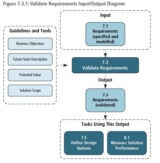
Techniques
- Acceptance and Evaluation Criteria: used to define the quality metrics that must be met to achieve acceptance by a stakeholder.
- Document Analysis: used to identify previously documented business needs in order to validate requirements.
- Financial Analysis: used to define the financial benefits associated with requirements.
- Item Tracking: used to ensure that any problems or issues identified during validation are managed and resolved.
- Metrics and Key Performance Indicators (KPIs): used to select appropriate performance measures for a solution, solution component, or requirement.
- Reviews: used to confirm whether or not the stakeholder agrees that their needs are met.
- Risk Analysis and Management: used to identify possible
Change management – Baselines, Change control Board, scope creep, gold plating
If it were possible to create a definitive set of requirements for a system once and only once, life would be much simpler, and there would be no need for this chapter. We could simply create a perfect Vision document, use-case model, and supplementary specification; freeze them for the duration of the development effort; and then declare everything past that point to be the responsibility of the maintenance team. Alas, things don't work that way. They never did in the past, and even with a more systematic approach to requirements management in the context of an iterative process, they will not work that way in the future.
Clearly, given the fact that change is a natural part of the process and that change will come from both external and internal sources, we need a process for managing change. Such a process puts the team in control so that it can effectively discover change, perform impact analysis, and incorporate those changes that are deemed both necessary and acceptable into the system in a systematic manner. Building on Weinberg's recommendations, a process for more effectively managing change must include the following steps.
- Recognize that change is inevitable, and plan for it.
- Baseline the requirements.
- Establish a single channel to control change.
- Use a change control system to capture changes.
- Manage change hierarchically.
Step 1: Recognize That Change Is Inevitable, and Plan for It
The first step is a simple one. The team must recognize that changing requirements for the system is inevitable and even necessary. Some amount of change will occur, and the team should develop an awareness of this issue and a corresponding plan for managing change that should include some allowance for change in the initial baseline. (Fortunately, if you've accepted the iterative development guidelines espoused in this book, you are already well on your way to this understanding.)
For example, requests for changes from the development team are legitimate since that team knows more about the system than anyone else does. Some of the "best" requirements come from the implementers who are closest to the system; they best recognize what the system really can do. We should encourage their input to the process since the result will be a better system for our users.
Baseline the Requirements
In each iteration, the team should baseline the requirements for the build. The baselining process may be as simple as putting version control on the pertinent artifacts—the Vision document, software requirements, and use-case models—and publishing the baseline for the development team. The collection of itemized requirements in these documents creates a baseline of information about the requirements and anticipated use cases for the system.
This simple step gives the team the ability to distinguish between known, or "old," requirements and new requirements (those being added, deleted, or modified and thus distinguishable from the "baseline" of known requirements). Once the baseline has been established, new requirements can be more easily identified and managed. A request for a new requirement can be compared against the existing baseline to see where it will fit in and whether it will create a conflict with any other requirements; this is often something that users overlook in their haste to respond to a change in their environment. If the change is accepted, we can manage the evolution of that change from the vision to the software requirements, from the software requirements to the appropriate technical design documents and models, and then to the code and the test procedures.
If this is done in an orderly, efficient, and responsive manner, the user community is likely to be much more cooperative. In the past, users in many organizations felt that they were being "stonewalled" by the technical development community when they asked for a change. Often, it was because the team had a chaotic, inefficient process for making the changes or because it was unable to describe the nature of that process to the users.
Step 3: Establish a Single Channel to Control Change
Ad hoc changes to a software system can easily cause significant and unintended consequences. Although it should be obvious that the existence of a new feature can cause significant impact to software requirements, system architecture, test plans, and so on, all of us have also experienced a worst case in which a "simple change" to code causes unanticipated consequences, occasionally even catastrophic ones. In addition, one proposed new feature might obviate, or make more difficult, an important future system feature that is not even being implemented in this release.
In addition, there is that thorny issue of the schedule and the budget for a project, which is typically the responsibility of the management team. The customer's wish for a change cannot be assumed to officially change the schedule and the budget, and a negotiation or budget reconciliation process must be initiated before a change can be approved.
Step 4: Use a Change Control System to Capture Changes
In a sense, it may be easiest to focus on the external, customer-requested changes because they are most readily identified and will tend to naturally find their way into the project via the project management or change control function. However, during development, there will be a tremendous number and variety of other types of potential changes to the system.
Indeed, many of the proposed changes that occur during the design, coding, and testing of a system may appear to be unrelated to requirements, involving corrections to code- or design-level bugs. However, the impact must still be assessed. And yes, as the deadline approaches, we must even make conscious decisions about which bugs will be allowed to remain in the system—due to the potential for the fix to destabilize the entire system and thereby jeopardize the release date—and which ones will be removed. Also, many bugs may affect the requirements, require interpolation between the requirements, or require disambiguation of a known requirement.
Step 5: Manage Change Hierarchically
The fact that all these people are interested in making changes to the system is not intrinsically bad; aside from the Easter Egg phenomenon, we could even imagine that all these changes are beneficial. However, the fact that the changes might not be documented or analyzed is a problem, and if they're not managed carefully, disaster can occur. A change to one requirement can have a ripple effect in other related requirements, the design, or other subsystems; further, this fact may not be obvious to the requester, who casually asks the programmer to make a "quick and easy" change to the system.
The problem is even worse without an explicit process. The changes typically occur in a "bottom-up" fashion. That is, if the change is envisioned while the code is being written for a new system, it's typically introduced directly into the code itself. If the developers are extremely disciplined, they might then ask themselves, "Hmmm, I wonder whether the changes we're making to the code will cause any changes in the design. Do the design-level changes have an impact on the requirements? And do the changes to the software requirements have any impact on the Vision document?" (Meanwhile, nobody remembers to tell any of this to the testing team, whose members thought they were supposed to be creating test plans for the original software requirements!)
In theory, it's possible to manage this "backward" ripple-effect phenomenon if all the respective documents are under the control of a sophisticated software tools environment. But even if all the documents are kept synchronized, the kind of bottom-up changes to the requirements that we've been discussing are still undesirable. To be blunt: a programmer doesn't have the authority to introduce new features and requirements directly into the code on the user's behalf, no matter how well intentioned. Similarly, the marketing representative who makes a casual request of the programmer for such a change, while they're both sipping a beer at the neighborhood brewpub, is not acting in an official capacity. Every new feature/requirement has an impact on the cost, schedule, reliability, and risk associated with the project.
Tracing requirements, allocating requirements – traceability matrix etc
Tracing Requirements
Traceability links allow you to follow the life of a requirement both forward and backward, from origin through implementation (Gotel and Finkelstein 1994). Traceability is one of the characteristics of excellent requirements specifications. To permit traceability, each requirement must be uniquely and persistently labeled so that you can refer to it unambiguously throughout the project. Write the requirements in a fine-grained fashion, rather than creating large paragraphs containing many individual functional requirements that lead to an explosion of design and code elements.
Next Figure illustrates four types of requirements traceability links (Jarke 1998). Customer needs are traced forward to requirements, so you can tell which requirements will be affected if those needs change during or after development. This also gives you confidence that the requirements specification has addressed all stated customer needs. Conversely, you can trace backward from requirements to customer needs to identify the origin of each software requirement. If you represented customer needs in the form of use cases, the top half of Figure 20-1 illustrates tracing between use cases and functional requirements.
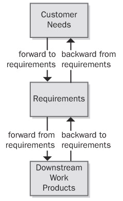
The bottom half of Figure indicates that, as requirements flow into downstream deliverables during development, you can trace forward from requirements by defining links between individual requirements and specific product elements. This type of link assures that you've satisfied every requirement because you know which components address each one. The fourth type of link traces specific product elements backward to requirements so that you know why each item was created. Most applications include code that doesn't relate directly to user-specified requirements, but you should know why someone wrote every line of code.
Suppose a tester discovers unexpected functionality with no corresponding written requirement. This code could indicate that a developer implemented a legitimate implied requirement that the analyst can now add to the specification. Alternatively, it might be "orphan" code, an instance of gold plating that doesn't belong in the product. Traceability links can help you sort out these kinds of situations and build a more complete picture of how the pieces of your system fit together. Conversely, test cases that are derived from—and traced back to—individual requirements provide a mechanism for detecting unimplemented requirements because the expected functionality will be missing.
Traceability links help you keep track of parentage, interconnections, and dependencies among individual requirements. This information reveals the propagation of change that can result when a specific requirement is deleted or modified. If you've mapped specific requirements to tasks in your project's work-breakdown structure, those tasks will be affected when a requirement is changed or deleted.
Figure illustrates many kinds of direct traceability relationships that can be defined on a project. You don't need to define and manage all these traceability link types. On many projects you can gain 80 percent of the desired traceability benefits for perhaps 20 percent of the potential effort. Perhaps you only need to trace system tests back to functional requirements or use cases. Decide which links are pertinent to your project and can contribute the most to successful development and efficient maintenance. Don't ask team members to spend time recording information unless you have a clear idea of how you expect to use it.
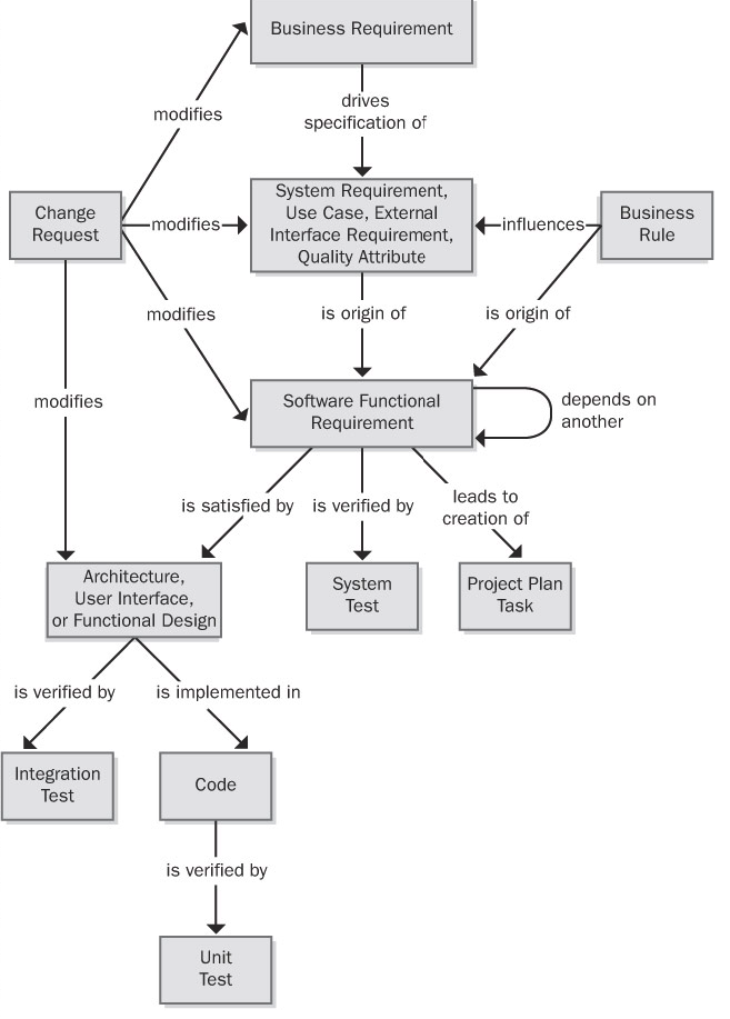
Figure: Some possible requirements traceability links.
Tracing requirements is a manually intensive task that requires organizational commitment. Keeping the link information current as the system undergoes development and maintenance takes discipline. If the traceability information becomes obsolete, you'll probably never reconstruct it. Obsolete traceability data wastes time by sending developers and maintainers down the wrong path. Because of these realities, you should adopt requirements traceability for the right reasons (Ramesh et al. 1995). Following are some potential benefits of implementing requirements traceability:
Certification You can use traceability information when certifying a safety-critical product to demonstrate that all requirements were implemented—although it doesn't confirm that they were implemented correctly or completely! Of course, if the requirements are incorrect or key requirements are absent, even the best traceability data won't help you.
Change impact analysis Without traceability information, there's a high probability of overlooking a system element that would be affected if you add, delete, or modify a particular requirement.
Maintenance Reliable traceability information facilitates making changes correctly and completely during maintenance, which improves your productivity. When corporate policies or government regulations change, software applications often require updating. A table that shows where each applicable business rule was implemented in the functional requirements, designs, and code makes it easier to make the necessary changes properly.
Project tracking If you diligently record the traceability data during development, you'll have an accurate record of the implementation status of planned functionality. Missing links indicate work products that have not yet been created.
Reengineering You can list the functions in a legacy system you're replacing and record where they were addressed in the new system's requirements and software components. Defining traceability links is a way to capture some of what you learn through reverse engineering of an existing system.
Reuse Traceability information facilitates reusing product components by identifying packages of related requirements, designs, code, and tests.
Risk reduction Documenting the component interconnections reduces the risk if a key team member with essential knowledge about the system leaves the project (Ambler 1999).
Testing When a test yields an unexpected result, the links between tests, requirements, and code point you toward likely parts of the code to examine for a defect. Knowing which tests verify which requirements can save time by letting you eliminate redundant tests.
Many of these are long-term benefits, reducing overall product life cycle costs but increasing the development cost by the effort expended to accumulate and manage the traceability information. View requirements tracing as an investment that increases your chances of delivering a maintainable product that satisfies all the stated customer requirements. Although difficult to quantify, this investment will pay dividends anytime you have to modify, extend, or replace the product. Defining traceability links is not much work if you collect the information as development proceeds, but it's tedious and expensive to do on a completed system.
The Requirements Traceability Matrix
Nonfunctional requirements such as performance goals and quality attributes don't always trace directly into code. A response-time requirement might dictate the use of certain hardware, algorithms, database structures, or architectural choices. A portability requirement could restrict the language features that the programmer uses but might not result in specific code segments that enable portability. Other quality attributes are indeed implemented in code. Integrity requirements for user authentication lead to derived functional requirements that are implemented through, say, passwords or biometrics functionality. In those cases, trace the corresponding functional requirements backward to their parent nonfunctional requirement and forward into downstream deliverables as usual. Figure 20-3 illustrates a possible traceability chain involving nonfunctional requirements.
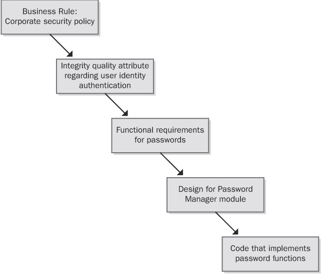
Traceability links can define one-to-one, one-to-many, or many-to-many relationships between system elements. The format in Table 20-1 accommodates these cardinalities by letting you enter several items in each table cell. Here are some examples of the possible link cardinalities:
- One-to-one One design element is implemented in one code module.
- One-to-many One functional requirement is verified by multiple test cases.
- Many-to-many Each use case leads to multiple functional requirements, and certain functional requirements are common to several use cases. Similarly, a shared or repeated design element might satisfy a number of functional requirements. Ideally, you'll capture all these interconnections, but in practice, many-to-many traceability relationships can become complex and difficult to manage.
Another way to represent traceability information is through a set of matrices that define links between pairs of system elements, such as these:
- One type of requirement to other requirements of that same type
- One type of requirement to requirements of another type
- One type of requirement to test cases