Competent
Patterns of Enterprise Architecture Applications:
Architectural Patterns: MVC
The Model-View-Controller (MVC) architectural pattern separates an application into three main components: the model, the view, and the controller.
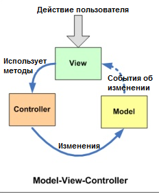
Основная идея этого паттерна в том, что и контроллер и представление зависят от модели, но модель никак не зависит от этих двух компонент.
Model
Модель – это данные вашего приложения, логика их получения и сохранения. Зачастую это модель предметной области (domain model), основанная на базе данных или на результатах от веб-сервисов. В некоторых случаях domain model хорошо проецируется на то, что вы видите на экране. Но иногда перед использованием ее необходимо адаптировать, изменить или расширить.
- это бизнес-логика приложения;
- обладает знаниями о себе самой и не знает о контроллерах и представлениях
View
в обязанности входит отображение данных полученных от Model. Однако, представление не может напрямую влиять на модель.
Можно говорить, что представление обладает доступом «только на чтение» к данным.
- в представлении реализуется отображение данных, которые получаются от модели любым способом;
- в некоторых случаях, представление может иметь код, который реализует некоторую бизнес-логику.
Controller
Controller обрабатывает действия пользователя и затем обновляет Model или View. Если пользователь взаимодействует с приложением (нажимает кнопки на клавиатуре, передвигает курсор мыши), контроллер получает уведомление об этих действиях и решает, что с ними делать.
Контроллер определяет, какие представление должно быть отображено в данный момент; События представления могут повлиять только на контроллер.контроллер может повлиять на модель и определить другое представление. Возможно несколько представлений только для одного контроллера;
Контроллер перехватывает событие извне и в соответствии с заложенной в него логикой, реагирует на это событие изменяя Mодель, посредством вызова соответствующего метода. После изменения Модель использует событие о том что она изменилась, и все подписанные на это события Представления, получив его, обращаются к Модели за обновленными данными, после чего их и отображают.
Architectural Patterns: IoC
Инверсия управления (Inversion of Control, IoC) это определенный набор рекомендаций, позволяющих проектировать и реализовывать приложения используя слабое связывание отдельных компонентов. То есть, для того чтобы следовать принципам Инверсии управления нам необходимо:
- Реализовывать компоненты, отвечающие за одну конкретную задачу;
- Компоненты должны быть максимально независимыми друг от друга;
- Компоненты не должны зависеть от конкретной реализации друг друга.
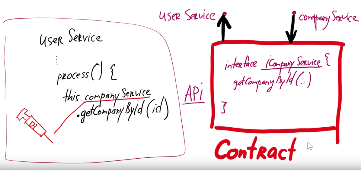
Одним из видов конкретной реализации данных рекомендаций является механизм Внедрения зависимостей (Dependency Injection, DI). Он определяет две основные рекомендации:
- модули верхних уровней не должны зависеть от модулей нижних уровней. Оба типа модулей должны зависеть от абстракций;
- абстракции не должны зависеть от деталей. Детали должны зависеть от абстракций.
То есть, если у нас будут существовать два связанных класса, то нам необходимо реализовывать связь между ними не напрямую, а через интерфейс. Это позволит нам при необходимости динамически менять реализацию зависимых классов.
InversifyJS
A powerful and lightweight inversion of control container for JavaScript & Node.js apps powered by TypeScript
interface INinja {
    fight(): string;
    sneak(): string;
}

interface IKatana {
    hit(): string;
}

interface IShuriken {
    throw();
}
import { inject } from "inversify";

class Katana implements IKatana {
    public hit() {
        return "cut!";
    }
}

class Shuriken implements IShuriken {
    public throw() {
        return "hit!";
    }
}
@inject("IKatana", "IShuriken")
class Ninja implements INinja {

    private _katana: IKatana;
    private _shuriken: IShuriken;

    public constructor(katana: IKatana, shuriken: IShuriken) {
        this._katana = katana;
        this._shuriken = shuriken;
    }

    public fight() { return this._katana.hit(); };
    public sneak() { return this._shuriken.throw(); };

}
import { Kernel } from "inversify";

import { Ninja } from "./entities/ninja";
import { Katana } from "./entities/katana";
import { Shuriken} from "./entities/shuriken";

const kernel = new Kernel();
kernel.bind<INinja>("INinja").to(Ninja);
kernel.bind<IKatana>("IKatana").to(Katana);
kernel.bind<IShuriken>("IShuriken").to(Shuriken);

export default kernel;
SOLID principles
S.O.L.I.D
SOLID это аббревиатура пяти основных принципов проектирования в объектно-ориентированном программировании. Эти принципы позволяют строить на базе ООП масштабируемые и сопровождаемые программные продукты с понятной бизнес-логикой.
Single responsibility (принцип единственной ответственности)
каждый объект должен иметь одну обязанность и эта обязанность должна быть полностью инкапсулирована в класс. Все его сервисы должны быть направлены исключительно на обеспечение этой обязанности.
Open-closed (принцип открытости / закрытости)
программные сущности (классы, модули, функции и т. п.) должны быть открыты для расширения, но закрыты для изменения. Это означает, что эти сущности могут менять свое поведение без изменения их исходного кода.
Liskov substitution (принцип подстановки Барбары Лисков)
функции, которые используют базовый тип, должны иметь возможность использовать подтипы базового типа не зная об этом
Interface segregation (принцип разделения интерфейса)
«клиенты не должны зависеть от методов, которые они не используют». Принцип разделения интерфейсов говорит о том, что слишком «толстые» интерфейсы необходимо разделять на более маленькие и специфические, чтобы клиенты маленьких интерфейсов знали только о методах, которые необходимы им в работе. В итоге, при изменении метода интерфейса не должны меняться клиенты, которые этот метод не используют.
Dependency inversion (принцип инверсии зависимостей)
модули верхних уровней не должны зависеть от модулей нижних уровней, а оба типа модулей должны зависеть от абстракций; сами абстракции не должны зависеть от деталей, а вот детали должны зависеть от абстракций.
Anti-patterns
- Copy-Paste Programming
- Spagetti code
- Golden Hummer (золотой молоток)
- Magic numbers
- Hard code
- Soft code (боязнь hard code)
- велосипеды
- God Object
Microservice architecture
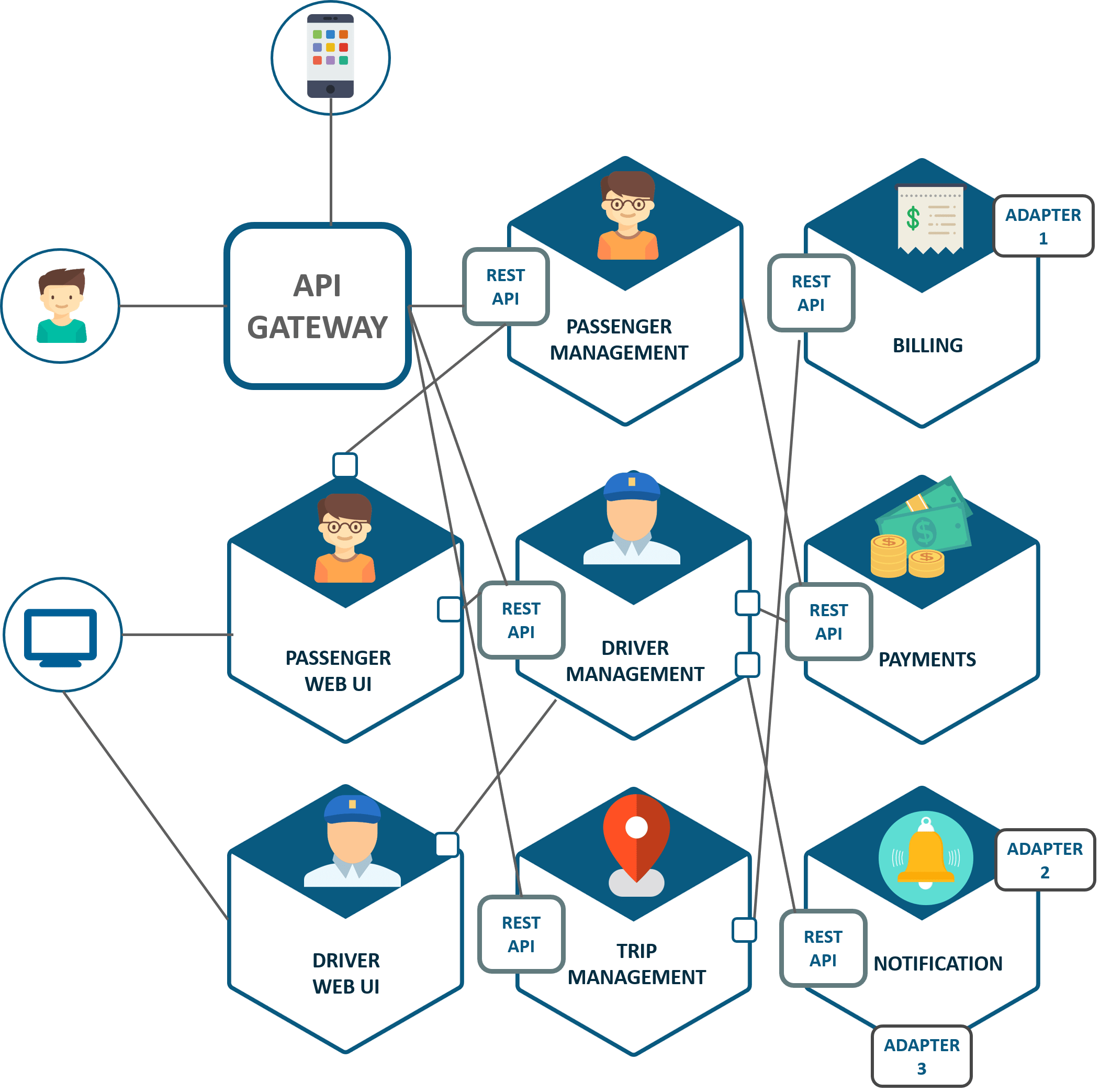
Microservices - also known as the microservice architecture - is an architectural style that structures an application as a collection of services that are
- Highly maintainable and testable
- Loosely coupled
- Independently deployable
- Organized around business capabilities.
- The microservice architecture enables the continuous delivery/deployment of large, complex applications. It also enables an organization to evolve its technology stack.
Benefits
- Componentization via Services
- Organized around Business Capabilities
- Products not Projects
- Smart endpoints and dumb pipes
- Decentralized Governance
- Decentralized Data Management
- Infrastructure Automation
- Design for failure
- Evolutionary Design
- Enables the continuous delivery and deployment of large, complex applications.
- Improved maintainability - each service is relatively small and so is easier to understand and change
- Better testability - services are smaller and faster to test
- Better deployability - services can be deployed independently
- It enables you to organize the development effort around multiple, autonomous teams. Each (so called two pizza) team owns and is responsible for one or more services. Each team can develop, test, deploy and scale their services independently of all of the other teams.
- Each microservice is relatively small:
- Easier for a developer to understand
- The IDE is faster making developers more productive
- The application starts faster, which makes developers more productive, and speeds up deployments
- Improved fault isolation. For example, if there is a memory leak in one service then only that service will be affected. The other services will continue to handle requests. In comparison, one misbehaving component of a monolithic architecture can bring down the entire system.
- Eliminates any long-term commitment to a technology stack. When developing a new service you can pick a new technology stack. Similarly, when making major changes to an existing service you can rewrite it using a new technology stack.
Disadvantages
- Distribution: Distributed systems are harder to program, since remote calls are slow and are always at risk of failure.
- Eventual Consistency: Maintaining strong consistency is extremely difficult for a distributed system, which means everyone has to manage eventual consistency.
- Operational Complexity: You need a mature operations team to manage lots of services, which are being redeployed regularly.
When to use the microservice architecture?
One challenge with using this approach is deciding when it makes sense to use it. When developing the first version of an application, you often do not have the problems that this approach solves. Moreover, using an elaborate, distributed architecture will slow down development. This can be a major problem for startups whose biggest challenge is often how to rapidly evolve the business model and accompanying application. Using Y-axis splits might make it much more difficult to iterate rapidly. Later on, however, when the challenge is how to scale and you need to use functional decomposition, the tangled dependencies might make it difficult to decompose your monolithic application into a set of services.
How to decompose the application into services?
Another challenge is deciding how to partition the system into microservices. This is very much an art, but there are a number of strategies that can help:
- Decompose by business capability and define services corresponding to business capabilities.
- Decompose by domain-driven design subdomain.
- Decompose by verb or use case and define services that are responsible for particular actions. e.g. a Shipping Service that’s responsible for shipping complete orders.
- Decompose by by nouns or resources by defining a service that is responsible for all operations on entities/resources of a given type. e.g. an Account Service that is responsible for managing user accounts.
- Ideally, each service should have only a small set of responsibilities. (Uncle) Bob Martin talks about designing classes using the Single Responsibility Principle (SRP). The SRP defines a responsibility of a class as a reason to change, and states that a class should only have one reason to change. It make sense to apply the SRP to service design as well.
Another analogy that helps with service design is the design of Unix utilities. Unix provides a large number of utilities such as grep, cat and find. Each utility does exactly one thing, often exceptionally well, and can be combined with other utilities using a shell script to perform complex tasks.
How to maintain data consistency?
In order to ensure loose coupling, each service has its own database. Maintaining data consistency between services is a challenge because 2 phase-commit/distributed transactions is not an option for many applications. An application must instead use the Saga pattern. A service publishes an event when its data changes. Other services consume that event and update their data. There are several ways of reliably updating data and publishing events including Event Sourcing and Transaction Log Tailing.
Layered Architecture
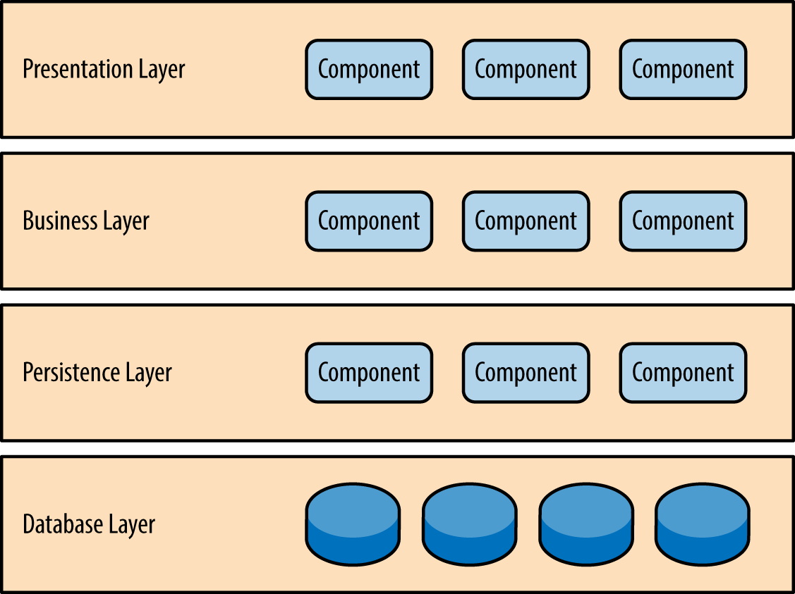
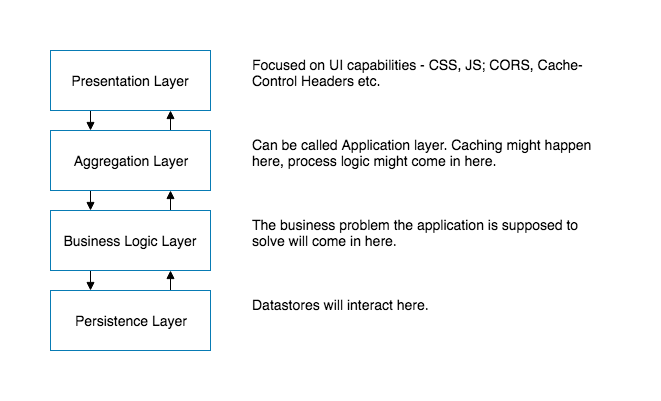
Components within the layered architecture pattern are organized into horizontal layers, each layer performing a specific role within the application (e.g., presentation logic or business logic). Although the layered architecture pattern does not specify the number and types of layers that must exist in the pattern, most layered architectures consist of four standard layers: presentation, business, persistence, and database
Each layer of the layered architecture pattern has a specific role and responsibility within the application. For example, a presentation layer would be responsible for handling all user interface and browser communication logic, whereas a business layer would be responsible for executing specific business rules associated with the request. Each layer in the architecture forms an abstraction around the work that needs to be done to satisfy a particular business request. For example, the presentation layer doesn’t need to know or worry about how to get customer data; it only needs to display that information on a screen in particular format. Similarly, the business layer doesn’t need to be concerned about how to format customer data for display on a screen or even where the customer data is coming from; it only needs to get the data from the persistence layer, perform business logic against the data (e.g., calculate values or aggregate data), and pass that information up to the presentation layer.
The UI Layer for example would often be driven by security and usability concerns. On the other hand, the Persistence Layer would be driven by data access, data security, and privacy concerns. By separating these concerns teams can ensure consistency and focus on their specific work. Developers working on the UI Layer don’t need to worry about privacy or data security as the Persistence Layer will ensure that data stored is secured, potentially encrypted, and that data access is controlled. Similarly, developers at the Persistence Layer don’t need to worry about how data is being displayed, how long text is handled, etc. Teams can become focused and achieve mastery at the layer that they are developing and maintaining.
Additionally, each layer has its own access control. This provides additional safe guards. Only the UI layer would traditionally be exposed to the internet — all underlying layers would be open only to layers above it. This ensures that there is a small attack surface.
Often these layers also match business functions of teams. A database team might maintain the database layer — ensuring servers are optimized and patched. A digital design team, or even a third party agency, may be maintaining the UI layer.
Advantages
The utopia of Layered Architecture is that one day we can swap out an Oracle DB with SQL Server and we would only need to only modify the Persistence Layer. All other layers will remain as is and will not even have to be tested after the Persistence Layer has been thoroughly vetted.
In reality, nobody is going to swap out a database, primarily because a production database has sensitive information that nobody wants to risk loosing during a migration attempt. Validating that the data migration was successful is equally painful and nobody’s idea of a desirable project.
It provides some cohesion in terms of team capabilities and clarities in terms of responsibilities. Presentation Layer folks may be highly skilled in Javascript and CSS and live confidently that nobody will ask them to performance tune a SQL query.
Security is heightened by a Layered Architecture. The Persistence Layer would typically be closed to the world and only open to the Business Logic Layer and the database itself. A hacker coming in through the UI Layer would have to hack multiple independent systems to finally penetrate to somewhere worth hacking into. Obviously, this may not always happen as organizations may get sloppy and be weak with the security of inter-layer communication.
Disadvantages
Layered Architectures introduce technological independence but inadvertently end up creating logical coupling across distributed environments.
A UI Layer may capture a profile change — e.g. a user updated their home address — this home address needs to travel through several layers, unmodified, to the Persistence Layer to finally be stored in a database. If for some reason this didn’t work, debugging will be challenging as we have to follow the data through several layers. The UI Layer can only talk to the layer directly below it (or in theory the layer directly above it). Any change within any of the intervening layers may have triggered the address to be lost. As a result layers become strongly coupled in terms of the API they can expose and the modifications they can make to their codebase.
There is an option to open up layers, but as Layered Architectures evolve teams adjust to reduce the need to modify many layers. They think in patterns that allow them to minimize changing more than one layer, essentially pigeon holing the architecture into a single corner. Developers may find that they don’t want to edit the UI Layer and the Aggregation Layer as that may require testing and debugging two layers including the network connection between them. Slowly, Layers become manipulated and drift into all purpose zones, and may even start resembling the big ball of mud.
Layered Architectures can succeed but need strong governance to ensure that feature creep doesn’t leave the layers porous.
Architectural Patterns: MVVM
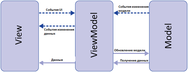
Данный подход позволяет связывать элементы представления со свойствами и событиями View-модели. Можно утверждать, что каждый слой этого паттерна не знает о существовании другого слоя.
Признаки View-модели:
- Двухсторонняя коммуникация с представлением;
- View-модель — это абстракция представления. Обычно означает, что свойства представления совпадают со свойствами View-модели / модели
- View-модель не имеет ссылки на интерфейс представления (IView). Изменение состояния View-модели автоматически изменяет представление и наоборот, поскольку используется механизм связывания данных (Bindings)
- Один экземпляр View-модели связан с одним отображением.
ViewModel не может общаться со View напрямую. Вместо этого она представляет легко связываемые свойства и методы в виде команд. View может привязываться к этим свойствам, чтобы получать информацию из ViewModel и вызывать на ней команды (методы). Это не требует того, чтобы View знала о ViewModel.
Вы получаете полностью тестируемую логическую модель вашего приложения.
Поскольку ViewModel предоставляет View всю необходимую информацию в удобном виде, то само представление может быть довольно простым.
вы можете избежать написания кода для View
Model View View-model (MVVM)
MVVM pattern supports two-way data binding between View and View-Model. This allows automatic propagation of changes, inside the state of View-Model to the View. Generally, the View-Model utilizes the observer pattern to inform changes in the View-Model to the Model.
View-Model
It is responsible for exposing methods, commands, and other properties that help to maintain the state of the view, manipulate the model as the result of actions on the view, and trigger events in the view itself. View has a reference to View-Model but View-Model has no information about the View. There is many-to-one relationship between View and View-Model means many Views can be mapped to one View-Model. It is completely independent of Views.
The bi-directional data binding or the two way data binding between the view and the View-Model ensures that the models and properties in the View-Model is in sync with the view. The MVVM design pattern is well suited in applications that need support for bi-directional data binding.
Event-Driven Architecture:
The event-driven architecture pattern is a popular distributed asynchronous architecture pattern used to produce highly scalable applications. It is also highly adaptable and can be used for small applications and as well as large, complex ones. The event-driven architecture is made up of highly decoupled, single-purpose event processing components that asynchronously receive and process events.
The event-driven architecture pattern consists of two main topologies, the mediator and the broker. The mediator topology is commonly used when you need to orchestrate multiple steps within an event through a central mediator, whereas the broker topology is used when you want to chain events together without the use of a central mediator. Because the architecture characteristics and implementation strategies differ between these two topologies, it is important to understand each one to know which is best suited for your particular situation.
The event-driven architecture pattern is a relatively complex pattern to implement, primarily due to its asynchronous distributed nature. When implementing this pattern, you must address various distributed architecture issues, such as remote process availability, lack of responsiveness, and broker reconnection logic in the event of a broker or mediator failure.
One consideration to take into account when choosing this architecture pattern is the lack of atomic transactions for a single business process. Because event processor components are highly decoupled and distributed, it is very difficult to maintain a transactional unit of work across them. For this reason, when designing your application using this pattern, you must continuously think about which events can and can’t run independently and plan the granularity of your event processors accordingly. If you find that you need to split a single unit of work across event processors—that is, if you are using separate processors for something that should be an undivided transaction—this is probably not the right pattern for your application.
Perhaps one of the most difficult aspects of the event-driven architecture pattern is the creation, maintenance, and governance of the event-processor component contracts. Each event usually has a specific contract associated with it (e.g., the data values and data format being passed to the event processor). It is vitally important when using this pattern to settle on a standard data format (e.g., XML, JSON, Java Object, etc.) and establish a contract versioning policy right from the start.
Broker Topology
The broker topology differs from the mediator topology in that there is no central event mediator; rather, the message flow is distributed across the event processor components in a chain-like fashion through a lightweight message broker (e.g., ActiveMQ, HornetQ, etc.). This topology is useful when you have a relatively simple event processing flow and you do not want (or need) central event orchestration.
There are two main types of architecture components within the broker topology: a broker component and an event processor component. The broker component can be centralized or federated and contains all of the event channels that are used within the event flow. The event channels contained within the broker component can be message queues, message topics, or a combination of both.
Since there is no central event mediator to receive the initial event in the broker topology, the customer-process component receives the event directly, changes the customer address, and sends out an event saying it changed a customer’s address (e.g., change address event). In this example, there are two event processors that are interested in the change address event: the quote process and the claims process. The quote processor component recalculates the new auto-insurance rates based on the address change and publishes an event to the rest of the system indicating what it did (e.g., recalc quote event). The claims processing component, on the other hand, receives the same change address event, but in this case, it updates an outstanding insurance claim and publishes an event to the system as an update claim event. These new events are then picked up by other event processor components, and the event chain continues through the system until there are no more events are published for that particular initiating event.
The broker topology is all about the chaining of events to perform a business function. The best way to understand the broker topology is to think about it as a relay race. In a relay race, runners hold a baton and run for a certain distance, then hand off the baton to the next runner, and so on down the chain until the last runner crosses the finish line. In relay races, once a runner hands off the baton, she is done with the race. This is also true with the broker topology: once an event processor hands off the event, it is no longer involved with the processing of that specific event.
Mediator Topology
The mediator topology is useful for events that have multiple steps and require some level of orchestration to process the event. For example, a single event to place a stock trade might require you to first validate the trade, then check the compliance of that stock trade against various compliance rules, assign the trade to a broker, calculate the commission, and finally place the trade with that broker. All of these steps would require some level of orchestration to determine the order of the steps and which ones can be done serially and in parallel.
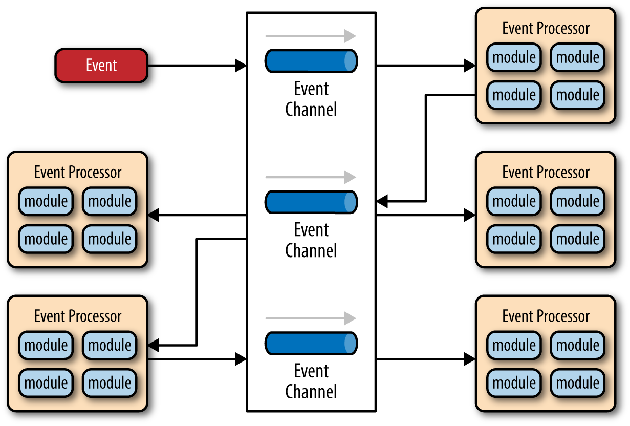
There are four main types of architecture components within the mediator topology: event queues, an event mediator, event channels, and event processors. The event flow starts with a client sending an event to an event queue, which is used to transport the event to the event mediator. The event mediator receives the initial event and orchestrates that event by sending additional asynchronous events to event channels to execute each step of the process. Event processors, which listen on the event channels, receive the event from the event mediator and execute specific business logic to process the event.
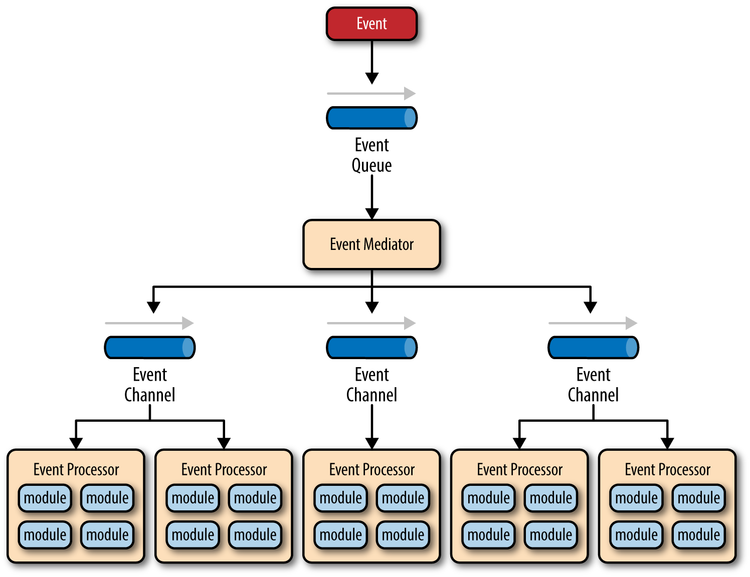
It is common to have anywhere from a dozen to several hundred event queues in an event-driven architecture. The pattern does not specify the implementation of the event queue component; it can be a message queue, a web service endpoint, or any combination thereof.
There are two types of events within this pattern: an initial event and a processing event. The initial event is the original event received by the mediator, whereas the processing events are ones that are generated by the mediator and received by the event-processing components.
The event-mediator component is responsible for orchestrating the steps contained within the initial event. For each step in the initial event, the event mediator sends out a specific processing event to an event channel, which is then received and processed by the event processor. It is important to note that the event mediator doesn’t actually perform the business logic necessary to process the initial event; rather, it knows of the steps required to process the initial event.
Event channels are used by the event mediator to asynchronously pass specific processing events related to each step in the initial event to the event processors. The event channels can be either message queues or message topics, although message topics are most widely used with the mediator topology so that processing events can be processed by multiple event processors (each performing a different task based on the processing event received).
The event processor components contain the application business logic necessary to process the processing event. Event processors are self-contained, independent, highly decoupled architecture components that perform a specific task in the application or system. While the granularity of the event-processor component can vary from fine-grained (e.g., calculate sales tax on an order) to coarse-grained (e.g., process an insurance claim), it is important to keep in mind that in general, each event-processor component should perform a single business task and not rely on other event processors to complete its specific task.
The event mediator can be implemented in a variety of ways. As an architect, you should understand each of these implementation options to ensure that the solution you choose for the event mediator matches your needs and requirements.
The simplest and most common implementation of the event mediator is through open source integration hubs such as Spring Integration, Apache Camel, or Mule ESB. Event flows in these open source integration hubs are typically implemented through Java code or a DSL (domain-specific language). For more sophisticated mediation and orchestration, you can use BPEL (business process execution language) coupled with a BPEL engine such as the open source Apache ODE. BPEL is a standard XML-like language that describes the data and steps required for processing an initial event. For very large applications requiring much more sophisticated orchestration (including steps involving human interactions), you can implement the event mediator using a business process manager (BPM) such as jBPM.
Understanding your needs and matching them to the correct event mediator implementation is critical to the success of any event-driven architecture using this topology. Using an open source integration hub to do very complex business process management orchestration is a recipe for failure, just as is implementing a BPM solution to perform simple routing logic.
To illustrate how the mediator topology works, suppose you are insured through an insurance company and you decide to move. In this case, the initial event might be called something like relocation event. The steps involved in processing a relocation event are contained within the event mediator. For each initial event step, the event mediator creates a processing event (e.g., change address, recalc quote, etc.), sends that processing event to the event channel and waits for the processing event to be processed by the corresponding event processor (e.g., customer process, quote process, etc.). This process continues until all of the steps in the initial event have been processed. The single bar over the recalc quote and update claims steps in the event mediator indicates that these steps can be run at the same time.
SOA (Basic)
A Service Oriented Architecture is a software architecture pattern, which application components provide services to other components via a communications protocol over a network. The communication can involve either simple data passing or it could involve two or more services coordinating connecting services to each other. Services (such as RESTful Web services) carry out some small functions, such as validating an order, activating account, or providing shopping cart services.
There are 2 main roles in SOA, a service provider and a service consumer. A software agent may play both roles. The Consumer Layer is the point where consumers (human users, other services or third parties) interact with the SOA and Provider Layer consists of all the services defined within the SOA. The following figure shows a quick view of an SOA architecture.
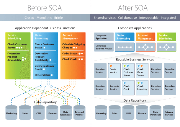
Enterprise Service Bus (ESB) is a style of the integration architecture that allows communication via a common communication bus that consists of a variety of point-to-point connections between providers and consumers . In addition to above, the data storage is shared within all services in SOA.
- SOA is widely used in market which responds quickly and makes effective changes according to market situations.
- The SOA keep secret the implementation details of the subsystems.
- It allows interaction of new channels with customers, partners and suppliers.
- It authorizes the companies to select software or hardware of their choice as it acts as platform independence.
Features
- SOA uses interfaces which solves the difficult integration problems in large systems.
- SOA communicates customers, providers and suppliers with messages by using the XML schema.
- It uses the message monitoring to improve the performance measurement and detects the security attacks.
- As it reuses the service, there will be lower software development and management costs.
Advantages
- SOA allows reuse the service of an existing system alternately building the new system.
- It allows plugging in new services or upgrading existing services to place the new business requirements.
- It can enhance the performance, functionality of a service and easily makes the system upgrade.
- SOA has capability to adjust or modify the different external environments and large applications can be managed easily.
- The companies can develop applications without replacing the existing applications.
- It provides reliable applications in which you can test and debug the independent services easily as compared to large number of code.
Disadvantages
- SOA requires high investment cost (means large investment on technology, development and human resource).
- There is greater overhead when a service interacts with another service which increases the response time and machine load while validating the input parameters.
- SOA is not suitable for GUI (graphical user interface) applications which will become more complex when the SOA requires the heavy data exchange.
SOA vs Microservices
Microservices Architecture vs. SOA As discussed above, both architectures have similar pros and cons and some differences. In both architectures, each service - unlike a monolithic architecture - has a certain responsibility. Thus, services can be developed in various technology stacks which bring technology diversity into the development team. The development of services can be organized within multiple teams, however, each team needs to know about the common communication mechanism in SOA.
In microservices, services can operate and be deployed independently of other services, unlike SOA. So, it is easier to deploy new versions of services frequently or scale a service independently.
In SOA, ESB could become a single point of failure which impacts the entire application. Since every service is communicating through ESB, if one of the services slow down, could cause the ESB to be clogged up with requests for that service. On the other hand, microservices are much better in fault tolerance. For example, if there is a memory leak in one microservice then only that microservice will be affected. The other microservices will continue to handle requests.
In both architectures, developers must deal with the complexity of architecture and a distributed system. Developers must implement the inter-service communication mechanism between microservices (if the message queue is used in Microservice architectures) or within ESB and services.
Unit Testing is more difficult as developers must mock the communication mechanism in tests. Due to many different service types, deployment and operational complexity are a concern in both architectures.
In SOA, services share the data storage (as shown in Figure 1) while each service can have an independent data storage in microservices. Sharing data storage has its pros and cons. for example, the data can be re-used by between all services while it brings dependency and tightly coupling within services.
Last but not least, the main difference between SOA and microservices lies in the size and scope. Microservice has to be significantly smaller than what SOA tends to be and mainly is a small(er) independently deployable service. On the other hand, an SOA can be either a monolith or it can be comprised of multiple microservices.
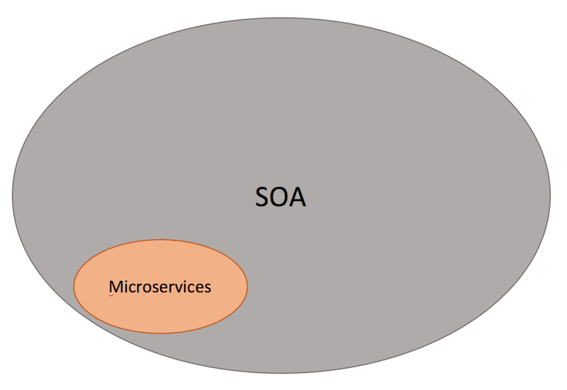
It is also important that SOA has been designed and implemented in various styles which could be different with what it is described here, usually due to a focus on ESBs which is used to integrate monolithic applications.
GoF
Design patterns provide solutions to common software design problems. In the case of object-oriented programming, design patterns are generally aimed at solving the problems of object generation and interaction, rather than the larger scale problems of overall software architecture. They give generalised solutions in the form of templates that may be applied to real-world problems.
Design patterns are a powerful tool for software developers. However, they should not be seen as prescriptive specifications for software. It is more important to understand the concepts that design patterns describe, rather than memorising their exact classes, methods and properties. It is also important to apply patterns appropriately. Using the incorrect pattern for a situation or applying a design pattern to a trivial solution can overcomplicate your code and lead to maintainability issues.
Creational Patterns
Creational patterns provide ways to instantiate single objects or groups of related objects
- Abstract Factory
- Builder
- Factory Method
- Prototype
- Singleton
Structural Patterns
Structural patterns provide a manner to define relationships between classes or objects.
- Adapter
- Bridge
- Composite
- Decorator
- Facade
- Flyweight
- Proxy
Behavioural Patterns
Behavioural patterns define manners of communication between classes and objects.
- Chain of Responsibility
- Command
- Interpreter
- Iterator
- Mediator
- Memento
- Observer
- State
- Strategy
- Template Method
- Visitor
Prototype
TIP
Создание объектов на основе шаблона существующего объекта клонированием A fully initialized instance to be copied or cloned
- в JS создаются объекты, которые действуют как прототипы для других объектов
- объект-прототип используется в качестве шаблона для каждого объекта, который создается конструктором
- для производительности, что функции хранятся в прототипе, а не в каждом экземпляре
class Sheep {

constructor(name, weight) {
    this.name = name;
    this.weight = weight;
}

clone() {
    return new Sheep(this.name, this.weight);
}
}

export default Sheep;
Abstract Factory
TIP
Шаблон абстрактная Фабрика предоставляет интерфейс для создания семейства связанных или зависимых объектов без точного определения их конкретных классов. Абстрактная фабрика – это интерфейс, который группирует другие фабрики, логически связанные друг с другом.
- Класс и подклассы, которые его реализут
TIP
Например, у нас есть несколько разных машин (Audi, BMW, Skoda) и несколько механиков, разбирающихся в конкретных машинах
class Car {
  // ...
}

class CarBMW {
  // ...
  getType() {
    return this.type; // BMW
  }
}

class CarAudi {
  // ...
  getType() {
    return this.type; // Audi
  }
}

class Mechanic {
  fix() { console.log('I can fix cars') }
}

class MechanicBMW {
  fix() { console.log('I can fix BMW') }
}
class MechanicAudi {
  fix() { console.log('I can fix BMW') }
}

class ServiceFactory {
  createCar() {
    return new Car();
  }
  createMechanic() {
    new Mechanic();
  }
}

class ServiceBMW {
    createCar() {
    return new CarBMW();
  }
  createMechanic() {
    new MechanicBMW();
  }
}
Adapter
TIP
Адаптер преобразует интерфейс для объекта или класса в интерфейс, совместимый с конкретной системой. This is a structural pattern where the interface of one class is translated into another. This pattern lets classes work together that could not otherwise because of incompatible interfaces.
TIP
Клиент делает запрос на адаптер, адаптер(предоставляет интерфейс, нужный клиенту) и посылает расширенный запрос Adaptee
Адаптеры в основном позволяют объединять объекты или классы, что обычно не может быть связано с их несовместимыми интерфейсами.
Адаптер переводит вызовы на свой интерфейс в вызовы на исходный интерфейс, а код, необходимый для достижения этого, обычно минимален.
classList.add||addClass
jQuery.fn.css()
class Soldier {
  constructor(level) {
    this.level = level;
  }

  attack() {
    return this.level * 1;
  }
}

class Jedi {
  constructor(level) {
    this.level = level;
  }

  attackWithSaber() {
    return this.level * 100;
  }
}

class JediAdapter {
  constructor(jedi) {
    this.jedi = jedi;
  }

  attack() {
    return this.jedi.attackWithSaber();
  }
}

export {
  Soldier,
  Jedi,
  JediAdapter
};
Composite
This is a structural design pattern that composes objects into tree-like structures to represent whole-part hierarchies. In this pattern, each node in the tree-like structure can be either an individual object or a composed collection of objects. Regardless, each node is treated uniformly.
The Composite pattern allows the creation of objects with properties that are primitive items or a collection of objects. Each item in the collection can hold other collections themselves, creating deeply nested structures.
A tree control is a perfect example of a Composite pattern. The nodes of the tree either contain an individual object (leaf node) or a group of objects (a subtree of nodes).
All nodes in the Composite pattern share a common set of properties and methods which supports individual objects as well as object collections. This common interface greatly facilitates the design and construction of recursive algorithms that iterate over each object in the Composite collection.
//Equipment
class Equipment {

  getPrice() {
    return this.price || 0;
  }

  getName() {
    return this.name;
  }

  setName(name) {
    this.name = name;
  }
}

// --- composite ---
class Composite extends Equipment {

  constructor() {
    super();
    this.equipments = [];
  }

  add(equipment) {
    this.equipments.push(equipment);
  }

  getPrice() {
    return this.equipments.map(equipment => {
      return equipment.getPrice();
    }).reduce((a, b) => {
      return a + b;
    });
  }
}

class Cabinet extends Composite {
  constructor() {
    super();
    this.setName('cabinet');
  }
}

// --- leafs ---
class FloppyDisk extends Equipment {
  constructor() {
    super();
    this.setName('Floppy Disk');
    this.price = 70;
  }
}

class HardDrive extends Equipment {
  constructor() {
    super();
    this.setName('Hard Drive');
    this.price = 250;
  }
}

class Memory extends Equipment {
  constructor() {
    super();
    this.setName('Memory');
    this.price = 280;
  }
}

export {
  Cabinet,
  FloppyDisk,
  HardDrive,
  Memory
};
Decorator
The Decorator pattern adds new behavior to objects dynamically at runtime wrapping itself around the original object. Multiple decorators can add or override functionality to the original object.
class Book {
  constructor(title, author, price) {
    this._title = title;
    this._author = author;
    this.price = price;
  }

  getDetails() {
    return `${this._title} by ${this._author}`;
  }
}

// decorator 1
function giftWrap(book) {
  book.isGiftWrapped = true;
  book.unwrap = function() {
    return `Unwrapped ${book.getDetails()}`;
  };

  return book;
}

// decorator 2
function hardbindBook(book) {
  book.isHardbound = true;
  book.price += 5;
  return book;
}

// usage
const alchemist = giftWrap(new Book('The Alchemist', 'Paulo Coelho', 10));

console.log(alchemist.isGiftWrapped); // true
console.log(alchemist.unwrap()); // 'Unwrapped The Alchemist by Paulo Coelho'

const inferno = hardbindBook(new Book('Inferno', 'Dan Brown', 15));

console.log(inferno.isHardbound); // true
console.log(inferno.price); // 20
Factory Method
Define an interface for creating an object, but let subclasses decide which class to instantiate. Factory Method lets a class defer instantiation to subclasses.
A Factory Method creates new objects as instructed by the client. One way to create objects in JavaScript is by invoking a constructor function with the new operator. There are situations however, where the client does not, or should not, know which one of several candidate objects to instantiate. The Factory Method allows the client to delegate object creation while still retaining control over which type to instantiate.
The key objective of the Factory Method is extensibility. Factory Methods are frequently used in applications that manage, maintain, or manipulate collections of objects that are different but at the same time have many characteristics (i.e. methods and properties) in common. An example would be a collection of documents with a mix of Xml documents, Pdf documents, and Rtf documents.
function Factory() {
    this.createEmployee = function (type) {
        var employee;

        if (type === "fulltime") {
            employee = new FullTime();
        } else if (type === "parttime") {
            employee = new PartTime();
        } else if (type === "temporary") {
            employee = new Temporary();
        } else if (type === "contractor") {
            employee = new Contractor();
        }

        employee.type = type;

        employee.say = function () {
            log.add(this.type + ": rate " + this.hourly + "/hour");
        }

        return employee;
    }
}

var FullTime = function () {
    this.hourly = "$12";
};

var PartTime = function () {
    this.hourly = "$11";
};

var Temporary = function () {
    this.hourly = "$10";
};

var Contractor = function () {
    this.hourly = "$15";
};

// log helper
var log = (function () {
    var log = "";

    return {
        add: function (msg) { log += msg + "\n"; },
        show: function () { alert(log); log = ""; }
    }
})();

function run() {
    var employees = [];
    var factory = new Factory();

    employees.push(factory.createEmployee("fulltime"));
    employees.push(factory.createEmployee("parttime"));
    employees.push(factory.createEmployee("temporary"));
    employees.push(factory.createEmployee("contractor"));

    for (var i = 0, len = employees.length; i < len; i++) {
        employees[i].say();
    }

    log.show();
}
Strategy
Encapsulates an algorithm inside a class
The Strategy pattern encapsulates alternative algorithms (or strategies) for a particular task. It allows a method to be swapped out at runtime by any other method (strategy) without the client realizing it. Essentially, Strategy is a group of algorithms that are interchangeable.
Say we like to test the performance of different sorting algorithms to an array of numbers: shell sort, heap sort, bubble sort, quicksort, etc. Applying the Strategy pattern to these algorithms allows the test program to loop through all algorithms, simply by changing them at runtime and test each of these against the array. For Strategy to work all method signatures must be the same so that they can vary without the client program knowing about it.
class ShoppingCart {

  constructor(discount) {
    this.discount = discount;
    this.amount = 0;
  }

  checkout() {
    return this.discount(this.amount);
  }

  setAmount(amount) {
    this.amount = amount;
  }
}

function guestStrategy(amount) {
  return amount;
}

function regularStrategy(amount) {
  return amount * 0.9;
}

function premiumStrategy(amount) {
  return amount * 0.8;
}

export {
  ShoppingCart,
  guestStrategy,
  regularStrategy,
  premiumStrategy
};
Template Method
Defer the exact steps of an algorithm to a subclass
class Tax {

  calc(value) {
    if (value >= 1000)
      value = this.overThousand(value);

    return this.complementaryFee(value);
  }

  complementaryFee(value) {
    return value + 10;
  }

}

class Tax1 extends Tax {

  constructor() {
    super();
  }

  overThousand(value) {
    return value * 1.1;
  }
}

class Tax2 extends Tax {

  constructor() {
    super();
  }

  overThousand(value) {
    return value * 1.2;
  }
}

export {
  Tax1,
  Tax2
};
Singleton
The Singleton Pattern ensures a class has only one instance, and provides a global point of access to it.
class Person {
  constructor() {
    if (typeof Person.instance === 'object') {
      return Person.instance;
    }
    Person.instance = this;
    return this;
  }
}

export default Person;
Mediator
Defines simplified communication between classes
The Mediator pattern provides central authority over a group of objects by encapsulating how these objects interact. This model is useful for scenarios where there is a need to manage complex conditions in which every object is aware of any state change in any other object in the group.
The Mediator patterns are useful in the development of complex forms. Take for example a page in which you enter options to make a flight reservation. A simple Mediator rule would be: you must enter a valid departure date, a valid return date, the return date must be after the departure date, a valid departure airport, a valid arrival airport, a valid number of travelers, and only then the Search button can be activated.
Another example of Mediator is that of a control tower on an airport coordinating arrivals and departures of airplanes.
class TrafficTower {

  constructor() {
    this.airplanes = [];
  }

  requestPositions() {
    return this.airplanes.map(airplane => {
      return airplane.position;
    });
  }
}

class Airplane {

  constructor(position, trafficTower) {
    this.position = position;
    this.trafficTower = trafficTower;
    this.trafficTower.airplanes.push(this);
  }

  requestPositions() {
    return this.trafficTower.requestPositions();
  }
}

export {
  TrafficTower,
  Airplane
};
Patterns of Enterprise Architecture Applications
Web Server Patterns
- Transform View (Преобразователь)
- Template View (Шаблонизатор)
- Application Controller (Контроллер приложения)
- Two Step View (Двухшаговая шаблонизация)
- Page Controller (Контроллер страницы)
- Front Controller (Контроллер входа / Единая точка входа)
- MVC - Model View Controller (Модель-Вид-Контроллер)
Concurrency Patterns
- Optimistic Offline Lock (Оптимистичная блокировка)
Предотвращает конфликты между конкурирующими бизнес-транзакциями, выявляя их и откатывая транзакцию назад. Тогда как Pessimistic Offline Lock подразумевает, что шанс сессии на конфликт высок и по этому ограничивает системную конкуренцию, Optimistic Offline Lock подразумевает, что шансы на конфликт не велики. Такое предположение не очень подходит для одновременной работы нескольких пользователей над одними данными.
- Pessimistic Offline Lock (Пессимистичная блокировка)
- Coarse Grained Lock (Грубая блокировка)
- Implicit Lock (Скрытая блокировка)
Base Patterns
Mapper (Распределитель)
Money (Деньги)
Огромное количество компьютеров в мире обрабатывают данные о деньгах. Удивительно, что класс Деньги до сих пор не является базовым в любом языке программирования. Недостаток такого рода типа данных приводит к проблемам, наиболее заметные из которых - работа с валютой. Если все вычисления в программе проделываются в одной валюте, никаких особых проблем нет, но как только вводится многовалютность - надо думать о том, чтобы не сложить 10 долларов с 10 йенами без перевода курсов валют. Менее заметна проблема с округлением. Денежные вычисления часто округляют до наименьшей из существующих мер. При этом легко не учесть копейки из-за ошибок округления.
Что действительно хорошо в ООП, так это то, что вы можете исправить эти проблемы, созданием класса Money (Деньги), чтобы работать с денежными величинами и избегать общих ошибок.
Special Case (Особый Случай)
Plugin (Плагин)
Соединяет классы во время конфигурации, а не компиляции.
Паттерн Separated Interface (Выделенный интерфейс) часто используется, когда один код выполняется в нескольких средах и требует разной реализации отдельной логики. Большинство разработчиков добиваются этого при помощи использования шаблона фабрики. Представим, что надо генерировать первичный ключ при помощи паттерна Separated Interface (Выделенный интерфейс). Можно использовать для юнит-тестирования простой объект-счёчик, а на реальной системе - последовательность из БД. Фабричный метод скорее всего будет содержать условный переход (if), проверяющий, установлен ли флаг тестирования, и возвращать необходимый генератор ключа.
Как только у вас появится ещё несколько фабрик - начнётся путаница. Создание новой конфигурации, например "запуск юнит-тестов на БД без контроля транзакций" или "запуск в продакшн на DB2 с полной поддержкой транзакций", потребует правок в условиях в большом количестве фабрик, пересборку и переразвёртывание.
Конфигурация не должна быть разбросана по приложению, также как и требовать пересборки и переразвёртывания. Паттерн Plugin решает обе эти проблемы, предоставляя централизованную динамическую конфигурацию.
Gateway (Шлюз)
Объект, который инкапсулирует доступ к внешней системе и ресурсу.
Separated Interface (Выделенный интерфейс)
Registry (Реестр)
Service Stub (Сервисная заглушка)
Value Object (Объект-значение)
Record Set ()
Layer Supertype (Супертип Уровня)
Singleton (Одиночка)
Flux
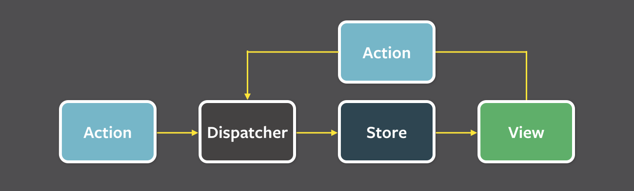
Flux следует концепции однонаправленного потока данных
- однонаправленный поток данных
- независимые хранилища данных
- синхронная обработка данных
ViewраспространяетActionчерез центральныйDispatcher, и это будет отправлено в различныеStores. Эти Stores будут отображать бизнес-логику приложения и другие данные. Store обновляет всеView.
Action- helper methods that create an action from method parameters, assign it a type and provide to DispatcherDispatcher- receives actions; sends them to stores via registered callbacksStore- receives actions from Dispatcher and update themselves; finally, emits a change eventView- controler-views listen for change events, retrieve new data from stores & prvides it to the entire tree or their child views