Competent
- Detailed OSI and TCP/IP models
- IP addressing protocols (DHCP, BOOTP, ARP)
- HTTP 2
- Mail protocols: POP3/IMAP/SMTP
- File sharing services: NFS, SMB, NetBIOS
- IPv4 transport and network layer protocols
- IP addressing: subnetting, CIDR and VLSM
- Unicast, Broadcast, Multicast
- NAT, Port Forwarding and DMZ
- Using network tools (tcpdump, nmap, WireShark)
- Secure connections with SSL/TLS (basic understanding)
- VPN and tunnels
- Basic understanding of IP routing
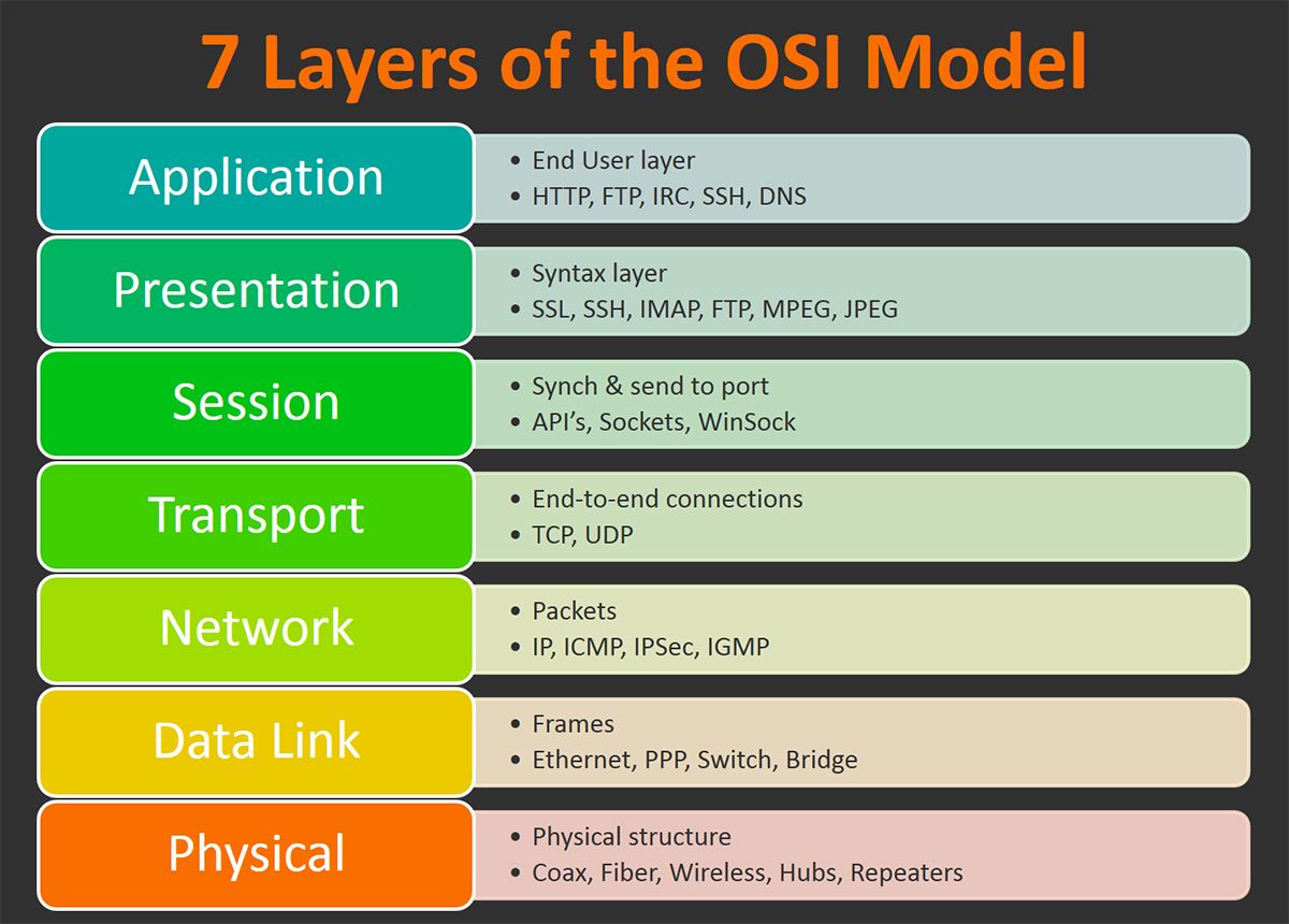
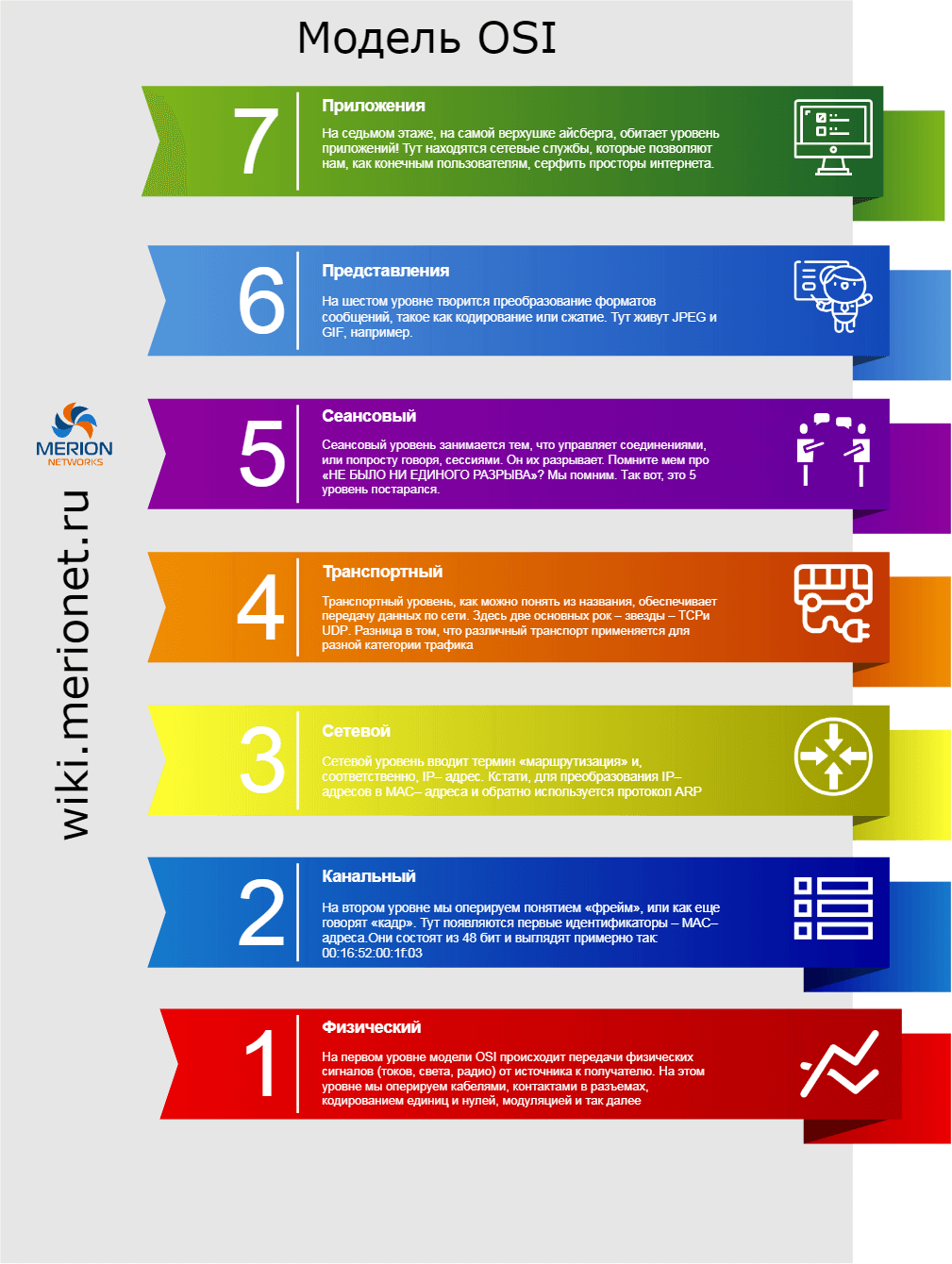
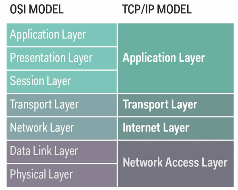
Detailed OSI and TCP/IP models
OSI
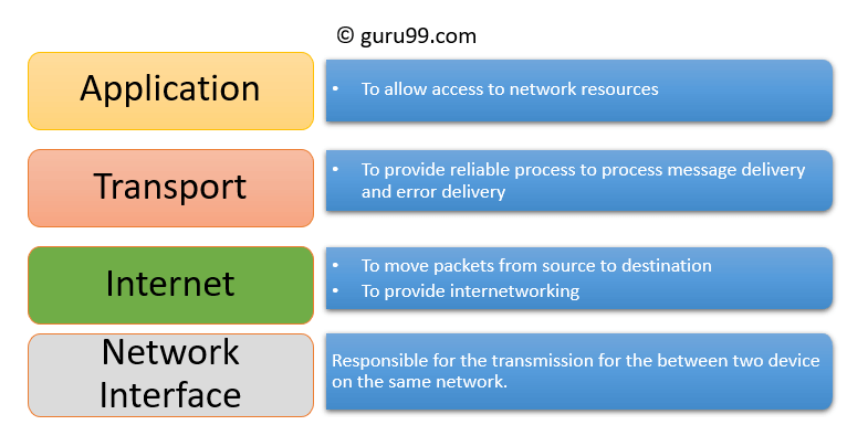
TCP/IP
IP addressing protocols (DHCP, BOOTP, ARP)
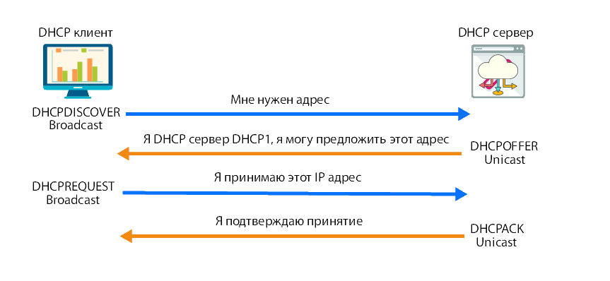
DHCP (Dynamic Host Configuration Protocol)
Каждому устройству, подключенному к сети, нужен уникальный IP-адрес. Сетевые администраторы назначают статические IP-адреса маршрутизаторам, серверам, принтерам и другим сетевым устройствам, местоположение которых (физическое и логическое) вряд ли изменится. Обычно это устройства, предоставляющие услуги пользователям и устройствам в сети, поэтому назначенные им адреса должны оставаться постоянными. Кроме того, статические адреса позволяют администраторам удаленно управлять этими устройствами – до них проще получить доступ к устройству, когда они могут легко определить его IP-адрес.
Однако компьютеры и пользователи в организации часто меняют места, физически и логически. Это может быть сложно и долго назначать новые IP-адреса каждый раз, когда сотрудник перемещается. А для мобильных сотрудников, работающих из удаленных мест, вручную настройка правильных параметров сети может быть весьма непростой задачей.
Использование DHCP в локальной сети упрощает назначение IP-адресов как на настольных, так и на мобильных устройствах. Использование централизованного DHCP-сервера позволяет администрировать все назначения динамических IP-адресов с одного сервера. Эта практика делает управление IP-адресами более эффективным и обеспечивает согласованность внутри организации, включая филиалы.
DHCPv4 динамически назначает адреса IPv4 и другую информацию о конфигурации сети. Отдельный сервер DHCPv4 является масштабируемым и относительно простым в управлении. Однако в небольшом офисе маршрутизатор может быть настроен для предоставления услуг DHCP без необходимости выделенного сервера.
DHCPv4 работает в режиме клиент/сервер. Когда клиент взаимодействует с сервером DHCPv4, сервер назначает или арендует IPv4-адрес этому клиенту. Он подключается к сети с этим арендованным IP-адресом до истечения срока аренды и должен периодически связываться с сервером DHCP, чтобы продлить аренду. Этот механизм аренды гарантирует, что клиенты, которые перемещаются или выходят из строя, не сохраняют за собой адреса, которые им больше не нужны. По истечении срока аренды сервер DHCP возвращает адрес в пул, где он может быть перераспределен по мере необходимости.
BOOTP (Bootstrap Protocol)
BOOTP - Bootstrap Protocol - предшественник DHCP. Тоже нужен для раздачи хостам L3-адресов и параметров, с акцентом на параметры, нужные для загрузки бездисковых рабочих станций и подобных им LWAPP.
В отличии от DHCP комплект опций, посылаемых клиенту, не может быть динамически модифицирован. Также BOOTP изначально заточен под двухфазовую схему работы - вначале дать клиенту минимум параметров, чтобы тот по TFTP скачал загрузочный образ и запустился, а потом продолжить.
BOOTP (Bootstrap Protocol) как и RARP обеспечивает определение с помощью специального сервера IP адреса клиента по его MAC адресу (например, при загрузке устройства, не имеющего возможности хранить свой собственный IP адрес), а также позволяет клиентам узнавать другие параметры загрузки (например, имя программы, загружаемой затем с помощью TFTP) и использует UDP в качестве протокола канального уровня. Это позволяет использовать маршрутизаторы (bootp relay) для передачи запросов и ответов из одного сегмента локальной сети в другой. Протокол DHCP (Dynamic Host Configuration Protocol) является надстройкой над BOOTP (для совместимости с bootp relay) и позволяет серверу выделять IP адреса клиентам динамически на ограниченный срок.
ARP (Address Resolution Protocol)
ARP (англ. Address Resolution Protocol — протокол определения адреса) — протокол канального уровня.
Протокол ARP (address resolution protocol, RFC-826, std-38) решает проблему преобразования IP-адреса в МАС-адрес.
Следует помнить, что у каждого узла в IP-сети есть как МАС-адрес, так и IP-адрес. Чтобы отправлять данные, узел должен использовать оба адреса.
Узел должен использовать собственные МАС- и IP-адреса в полях источника, а также предоставить МАС- и IP-адреса для назначения. Несмотря на то, что IP-адрес назначения будет предоставлен более высоким уровнем OSI, отправляющему узлу необходим способ найти MAC-адрес назначения для данного канала Ethernet. В этом заключается назначение протокола ARP.
В своей работе ARP полагается на конкретные типы широковещательных и одноадресных сообщений Ethernet, которые также называются запросами и ответами ARP.
Протокол ARP выполняет две основные функции:
- сопоставление адресов IPv4 и МАС-адресов
- сохранение таблицы сопоставлений

Устройству 3го уровня необходим протокол ARP для сопоставления IP-адреса с MAC-адресом, для отправки IP пакетов. Прежде чем устройство отправит данные на другое устройство, оно заглянет в свой кеш ARP где хранятся все сопоставления IP и MAC адресов, чтобы узнать, есть ли MAC-адрес и соответствующий IP-адрес для устройства, которому идет отправка. Если записи нет, то устройство-источник отправляет широковещательное сообщение каждому устройству в сети чтобы узнать устройству с каким MAC-адресом принадлежит указанный IP-адрес. Все устройства сравнивают IP-адрес с их собственным и только устройство с соответствующим IP-адресом отвечает на отправляющее устройство пакетом, содержащим свой MAC-адрес. Исходное устройство добавляет MAC-адрес устройства назначения в свою таблицу ARP для дальнейшего использования, создает пакет с новыми данными и переходит к передаче.
HTTP 2
HTTP/2 это старшая версия сетевого протокола HTTP. Основным назначеним HTTP/2 является снижение задержки(latency) путём реализации полного мультиплексирования запросов и ответов, уменьшения перегруженности протокола при помощи эффективного сжатия заголовков HTTP, а также добавления поддержки приоритетов запроса и "server push"("серверне проталкивание" - сервер имея правила, может проявить инициативу, которые инициируют отправку контента до его запроса, зная о том, что может поступить запрос на их отправку).
HTTP/2 никоим образом не изменяет семантику применяемую HTTP. Все основные концепции HTTP 1.1, такие как методы HTTP, коды статусов, URI, и поля заголовков останутся прежними. Вместо этого HTTP/2 изменит порядок(форму) данных и способ их передачи между клиентом и сервером, которые управляют всем процессом, и скроет сложность применения в новом обрамляющем слое. Это позволит использовать существующие приложения без изменений.
Бинарный HTTP/2 по сравнению с HTTP имеет измененные способы разбиения данных на фрагменты и транспортирования их между сервером и клиентом. Обновленное нововведение HTTP/2 предназначено для лучшей, эффективной и безопасной работы сайтов в современном Интернете.
Главные преимущества при переходе на новый протокол – это увеличение скорости загрузки сайтов и улучшение ранжирования проекта в поиске.
Все сайты работают на основе протокола HTTP/1.1, но с ростом и развитием Интернет размер онлайн-проектов значительно вырос. Для загрузки одной страницы передается около 1,9 МБ данных. Данный протокол стал хуже справляться с нагрузкой, но, конечно же, ускорить загрузку сайтов можно специальными методами: подключить CDN, сделать настройку кэширования, удалить ненужные символы из javascript и CSS, распределить проект по разным хостам и т.д. Правда, не все эти методы на деле оказываются действительно эффективными и нужными. Поэтому в 2009 году началась разработка нового протокола, который должен решить проблемы связанные с медленной загрузкой сайтов в Сети и улучшением производительности. Нововведение HTTP/2 основано на протоколе SPDY и совместимо с HTTP/1.1.
Какие улучшения применены в HTTP/2?
Прежде всего, это наличие только одного соединение с сервером, которое снижает количество циклов, необходимых для установления множественных TCP-соединений. Оно остается открытым столько, сколько открыт сам сайт. Второе улучшения: наличие мультиплексирования. Множественные запросы работают одновременно на одном и том же соединении. Применение технологии Server Push. Дополнительные ресурсы могут посылаться клиенту для использования в будущем.Функция определения приоритетов, при которой запросам назначаются уровни зависимости. Сервер может ими пользоваться и в итоге приоритетную информацию доставлять быстрее.Бинарность протокола: простота, компактность и меньше ошибок. Не нужно времени для перевода текстовой информации в бинарный код.
HTTP/2 работает быстрее за счет того, что несколько запросов передаются в рамках одного соединения, служебные HTTP-заголовки сжимаются, повышение безопасности – не нужно дополнительного шифрования для HTTP/2 , смена порядка приоритезации. Как видим, новый протокол принесет много преимуществ.
Стоит ли Вашему сайту сейчас переходить на данный протокол? Все зависит от особенностей Вашего сайта. Если большинство посетителей Вашего ресурса пользуются браузерами Chrome, Firefox, Opera, Edge, Safari, то это уже плюс в пользу перехода, так как HTTP/2 поддерживается данными браузерами. Ваш сайт имеет много мобильного трафика? Тогда данный переход станет полезным, хотя браузер Opera Mini, которым иногда пользуются с мобильных устройств, пока не поддерживает данный протокол. Есть также свои специфические особенности, например, Internet Explorer 11 поддерживает HTTP/2 только при установленной Windows 10. Если у Вас в планах запустить новый онлайн проект, стоит задуматься о новом протоколе и учесть все его преимущества.
Как взаимодействуют версии протокола HTTP/1.1 и HTTP/2?
Если браузер пользователя не поддерживает новый HTTP/2, то он просто понижает соединение до HTTP/1.1. Чтобы сайт начал поддержку нового протокола, в большинстве случаев необходимо обновить программное обеспечение сервера. Правда, большинство популярных браузеров поддерживают вторую версию только при наличии безопасного соединения. В данном случае можно воспользоваться бесплатным сертификатом TLS.
В любом случаи пользователи оценят такой переход, ведь скорость загрузки сайтов увеличится, соответственно ускоряется сам процесс работы. Для мобильных сетей протокол еще более существенно уменьшает время загрузки, что является особым преимуществом при переходе на HTTP/2, в случае, если у Вашего ресурса много мобильного трафика.
4 особенности оптимизации сайта под новый протокол HTTP/2: объединение изображений в спрайты для улучшения сжатия, что, в свою очередь, уменьшает общий объем снижаемых данных; следует отказаться от встраивания изображений с помощью DataURI, что только ухудшает производительность в HTTP/2; от конкатенации JS и CSS можно также вполне отказаться, в случае, если HTTP-запросы не требуют существенных затрат ресурсов; нет необходимости в доменном шардировании, потому что оно создает дополнительные TCP-соединения и ухудшает производительность работы. Простые 4 правила помогут любому веб-разработчику подготовить сайт к новому протоколу уже на этапе создания ресурса.
Большинство видов серверного ПО (в частности Apache, NGINX, and IIS) поддерживает HTTP/2. Некоторые главные системы доставки контента (CDN) также имеют поддержку нового протокола (включая Akamai).
Преимущества перехода на протокол http2
- Производительность сайта увеличивается благодаря тому, что запросы объединяются в одно TCP-соединение.
- Статистические элементы получают параллельный запрос.
- Запросы получают приоритет, при этом учитывается вес и их зависимости.
- Происходит сжатие HTTP-заголовков и уменьшение объема данных обмена между браузером и сервером.
- Обеспечивается безопасность соединения за счет подключения TLS шифрования (SSL сертификата).
- Push сервер подразумевает одновременную загрузку дополнительных файлов вместе с основным. Кэш браузера может быть обновлен или удален.
- Ресурсы хранятся в кэше.
- Для одинаковых задач используются двоичные команды 1 и 0 в процессе выполнения.
Mail protocols: POP3/IMAP/SMTP
POP3
POP3 (Post Office Protocol version 3) is a one-way incoming mail protocol that downloads a copy of messages from an email server to a local machine. Once the protocol completes the process, it deletes the original data from the server’s inbox.
However, many providers these days give an option to keep the original copies intact, allowing users to see the same content when accessing messages from a different platform.
In general, we recommend this setting for people who only use one device to access emails and want to view their messages offline. It’s also useful for those who want to free up an inbox’s space that almost exceeds its capacity.
Do keep in mind that this protocol cannot sync the content of your offline inbox with its online counterpart by default. So if the device that stores the messages is lost or broken, you could lose all of the ones you’ve saved.
Default POP3 Ports:
- Port 110 – non-encrypted port
- Port 995 – SSL/TLS port, also known as POP3S
IMAP
IMAP (Internet Message Access Protocol), as opposed to POP3, is a two-way incoming mail protocol that only downloads email headers instead of its entire content.
As a result, the actual email messages are still kept on the server after being fetched for viewing, making them accessible from another platform. This protocol also syncs whatever changes made on the email client to the server, hence the two-way communication.
This configuration is recommended for those who want to interact with their email messages across multiple devices, so you don’t have to worry about losing important ones should a device is broken or stolen. Another perk of using IMAP is the ease of finding a specific message using a keyword.
However, you need to have a stable internet connection to gain full access to all the emails stored in the IMAP server. The email account’s storage space limit can also pose some issues to your messages, especially if you use it in high intensity.
Default IMAP ports:
- Port 143 – non-encrypted port
- Port 993 – SSL/TLS port, also known as IMAPS
SMTP
Now that we have learned about the incoming protocols, POP3 vs IMAP, let’s take a look at the one used to handle outgoing emails.
Simple Mail Transfer Protocol (SMTP) is used to send emails from a local client to a recipient’s address. It works side-by-side with a software called Message Transfer Agent (MTA) to transfer electronic messages to their correct destinations.
Aside from sending emails, this protocol also acts as a safeguard to filter which message passes through. It regulates the limit of how many messages an account can send within a time frame.
Default SMTP ports:
- Port 25 – non-encrypted port
- Port 465 – SSL/TLS port, also known as SMTPS
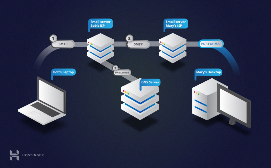
How Does Sending and Receiving Emails Work? An email message travels through at least two main SMTP servers that belong to the senders and the recipients.
First, SMTP connects your client with your email provider’s server. Next, it checks the email header for relevant information about the sender and the recipient’s address.
Once a destination is determined, the server will check the location of the domain associated with the address in the Domain Name System.
For example, if you are trying to send a message to emailuser@gmail.com, the server locates gmail.com and relays the message to that specific computer.
Then, the recipient’s SMTP server delivers the message to the server’s mailbox until the intended user logs in to their email account. When that happens, either POP3 or IMAP will forward the new message to the recipient’s email client so they can view it.
In this POP3 vs IMAP article, we have learned that they are intended for the same purpose but have a different approach with IMAP leaving email content on the server and POP3 downloading it all to your computer. We have also learned about SMTP and the ports used by these three components.
File sharing services: NFS, SMB, NetBIOS
NFS
The Network File System (NFS) is a client/server application that lets a computer user view and optionally store and update files on a remote computer as though they were on the user's own computer. The NFS protocol is one of several distributed file system standards for network-attached storage (NAS).
NFS allows the user or system administrator to mount (designate as accessible) all or a portion of a file system on a server. The portion of the file system that is mounted can be accessed by clients with whatever privileges are assigned to each file (read-only or read-write). NFS uses Remote Procedure Calls (RPCs) to route requests between clients and servers.
NFS was originally developed by Sun Microsystems in the 1980's and is now managed by the Internet Engineering Task Force (IETF). NFSv4.2 (RFC-7862) was ratified in November 2016 as a set of extensions to NFSv4 (RFC-3530).
Network File System versions 2 and 3 allow the User Datagram Protocol (UDP) running over an IP network to provide stateless network connections between clients and server, but NFSv4.2 requires use of the Transmission Control Protocol (TCP).
NFS advantages
NFS is a low-cost solution for network file sharing that is easy to setup as it uses the existing IP infrastructure. A significant advantage of NFS is that it allows for central management, decreasing the need for added software and disk space on individual user systems. NFS is user-friendly, allowing users to access files on remote hosts in the same way they access local files. This reduces the need for removable media storage devices and increases security as fewer CDs, DVDs, Blu-Ray disks, diskettes and USB drives are in circulation.
NFS disadvantages
NFS is based on RPCs which are inherently insecure and should only be used on a trusted network behind a firewall. Otherwise, NFS will be vulnerable to internet threats. Some reviews of NFSv4 and NFSv4.1 suggest that these versions have limited bandwidth and scalability (improved with NFSv4.2) and that NFS slows down during heavy network traffic.
SMB
Server Message Block (SMB) is the Internet standard protocol Windows uses to share files, printers, and serial ports. In a networked environment, servers make file systems and resources available to clients. Clients make SMB requests for resources, and servers make SMB responses in what's described as a client server, request-response protocol.
The SMB protocol can be used over the Internet on top of its TCP/IP protocol or on top of other network protocols. Using the SMB protocol, an application (or the user of an application) can access files at a remote server, as well as other resources, including printers. Thus, a client application can read, create, and update files on the remote server. It can also communicate with any server program that is set up to receive an SMB client request.
Microsoft Windows operating systems since Windows 95 include client and server SMB protocol support. For Unix type systems, like Linux and Mac OS X, an open source application called Samba is available which, when installed and properly configured, allows SMB interoperability between those operating systems and Windows.
NetBIOS
NetBIOS (/ˈnɛtbaɪɒs/) is an acronym for Network Basic Input/Output System. It provides services related to the session layer of the OSI model allowing applications on separate computers to communicate over a local area network. As strictly an API, NetBIOS is not a networking protocol. Older operating systems[clarification needed] ran NetBIOS over IEEE 802.2 and IPX/SPX using the NetBIOS Frames (NBF) and NetBIOS over IPX/SPX (NBX) protocols, respectively. In modern networks, NetBIOS normally runs over TCP/IP via the NetBIOS over TCP/IP (NBT) protocol. This results in each computer in the network having both an IP address and a NetBIOS name corresponding to a (possibly different) host name.
IPv4 transport and network layer protocols
Just about everyone in the networking industry talks about interoperability; the U.S. Department of Defense (DOD), in the guise of the ARPANET (Advanced Research Projects Agency Network) project, actually did something about it when it created the Transmission Control Protocol/Internet Protocol (TCP/IP) family of networking protocols.
TCP/IP is the DOD's answer to connecting its rapidly proliferating—and widely dissimilar—computers and networks into a loosely associated wide area network (now called the Internet). TCP/IP is the DOD's vehicle for providing distributed computing capabilities across a large area. TCP/IP might also be called the less talented but still much in demand ugly stepsister to the International Standards Organization's (ISO) Open System Interconnection (OSI) protocols. Though the OSI protocols were designed to dominate the computer environment, TCP/IP remains the central piece in the complex interoperability puzzle.
As its two-part name implies, TCP/IP encompasses more than one protocol. It includes a range of protocols that provide distinct services and capabilities necessary for communication between and control of otherwise incompatible computers and networks. In addition to the Transmission Control Protocol (TCP) and Internet Protocol (IP), these include the File Transfer Protocol (FTP), the Simple Mail Transfer Protocol (SMTP), the Internet Control Message Protocol (ICMP), and the Simple Network Management Protocol (SNMP).
Other protocols within the TCP/IP family are the Address Resolution Protocol (88), the Reverse Address Resolution Protocol (RARP), the Exterior Gateway Protocol (EGP), and the User Datagram Protocol (UDP). IP, TCP, FTP, SMTP, and Telnet were part of the original DOD military standard, TCP/IP protocol suite promulgated in the late 1970s. Although TCP/IP was the brainchild of and for the military, it has become the de facto protocol for general-purpose intersystem communication.
The TCP/IP Protocols
Each TCP/IP protocol provides a specific service or set of services to move data from one computer to network to computer. The services some of these provide—the File Transfer Protocol (FTP), for instance—are self-explanatory. Others aren't so obvious. In the lexicon of the TCP/IP world, an interconnected set of networks is called an internet; the Internet Protocol (IP) is responsible for accepting segmented data (in the form of a Protocol Data Unit, or PDU) from a host computer and sending it across the Internet through the required gateways until the data reaches its destination.
The IP delivery process provides what is known as an unreliable connectionless service; proper delivery is not guaranteed by IP. Even PDUs that are delivered may arrive at the destinations out of sequence. TCP must ensure reliable delivery of PDUs. TCP provides the transport mechanism that ensure that data is delivered error-free, in the order it was sent, and without loss or duplication. TCP's basic role is providing reliable end-to-end data transfer between two processes, called transport users (these include FTP and SMTP). In specific terms, the TCP standard describes five levels of service: multiplexing (the ability to support multiple processes), connection management, data transport, error reporting, and a variety of special capabilities.
In the basic data-transfer process, a transport user such as FTP passes data to TCP, which encapsulates the data into a segment that contains user data and control information (e.g., the destination address). TCP ensures reliable data delivery by numbering outgoing segments sequentially and then having the destination TCP module acknowledge arrival by number. If segments arrive out of order, they can be reordered via sequence numbers, and if a segment fails to arrive, the destination TCP module will not acknowledge its receipt, and the sending TCP module resends it.
TCP allows the transport user to specify the quality of transmission service it requires, permits special urgent data transmissions, and provides security classifications that can be used in routing segments to data-encryption devices. In trying to provide high-quality transmission services, TCP attempts to optimize the underlying IP and network resources. Parameters available include timeout delays and message-delivery precedence. Interrupt-driven urgent transmissions include terminal-generated break characters and alarm conditions. The services provided by TCP and IP are defined by primitives and parameters. A primitive is a mechanism for specifying the function to be performed, while parameters are used to pass data and control information.
Only two primitives—SEND and DELIVER—are used to define the IP services. Parameters available with these primitives include source and destination host addresses, the recipient protocol (usually TCP), an identifier that distinguishes one user's data from another's, and user data.
TCP offers two primitives and associated parameters: service request and service response primitives. A TCP client sends service request primitives to TCP; TCP issues the service response primitives to the client. Many of these primitives set off an exchange of TCP segments between host processes or computers, and TCP passes the segments to IP in a SEND primitive and receives them from IP in a DELIVER primitive.
Files And Terminals
FTP exists to transfer a file or a portion of a file from one system to another under orders from an FTP user. Typically, a user executes FTP interactively through an operating system interface, which provides the input/output facilities that allow exchanging files between systems.
FTP options allow transferring ASCII and EBCDIC character sets and using transparent bit streams that permit exchanging any sort of data or text file. FTP also provides data-compression options and has password/identifier mechanisms for controlling user access.
SMTP provides the underlying capabilities for a network electronic mail facility. It does not, however, provide the user interface. Primarily, it provides mechanisms for transferring messages between separate systems. SMTP accepts e-mail messages prepared by a native mail facility (such as cc:Mail) and—making use of TCP to send and receive messages across the network— delivers them. With SMTP, users can send mail to users anywhere in the local network as well as to those on the Internet.
TELNET outlines a network terminal-emulation standard. It allows terminals to connect to and control applications running in a remote host just as if it were a local user of the host.
In implementation, TELNET takes two forms: user and server modules. The user module interacts with the terminal I/O module, providing translation of terminal characteristics into the network-specific codes and vice versa. The server module interacts with processes and applications, serving as a terminal handler to make remote terminals look as if they are local.
SNMP And Other Protocols
Among the other TCP/IP protocols, one of the most widely applied is SNMP, the Simple Network Management Protocol. SNMP supports the exchange of network management messages among hosts, including a central host that is often called a network management console.
SNMP was designed to operate over UDP, the User Datagram Protocol. UDP operates at the same level as TCP, providing a connectionless service for the exchange of messages while avoiding the overhead of TCP's reliability facilities.
ARP and RARP provide mechanisms for hosts to learn MAC and Internet addresses. The former allows a host to discover another host's MAC address, and the latter permits a host to find out its own Internet address, an important capability for diskless PCs without permanent ways to store their Internet addresses.
The Exterior Gateway Protocol allows neighboring gateways in different autonomous systems to exchange information about which networks are accessible via a particular gateway. Industry observers once predicted that most TCP/IP users would eventually migrate to OSI. The question is, when? Few commercially available products offer complete OSI functionality. Most OSI protocols remain in the standards-setting phase, and users continue to be satisfied with the level of service provided by TCP/IP.
IP addressing: subnetting, CIDR and VLSM
Subnetting
That issue of IP address wastage brings us to the topic at hand – Subnetting. Subnetting allows you to create smaller network (sub networks; subnets) inside a large network by borrowing bits from the Host ID portion of the address. We can use those borrowed bits to create additional networks, resulting in smaller-sized networks.
- Network #1: 192.168.1.0
- Network #2: 192.168.2.0
Each of these networks will support 254 IP addresses leading to a wastage of (254 * 4) – (30 * 4) IP addresses i.e. 896 IP addresses!
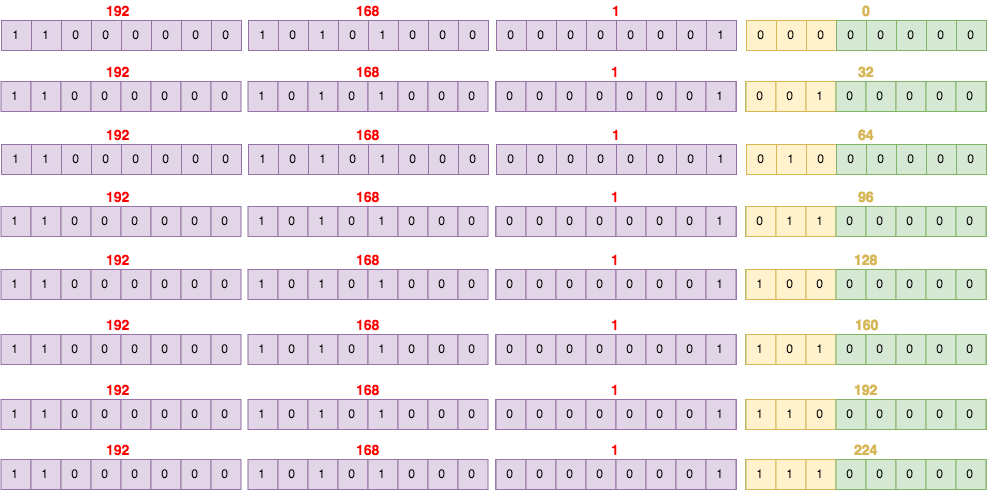
By borrowing 3 bits, I can create 8 subnets:
- 192.168.1.0
- 192.168.1.32
- 192.168.1.64
- 192.168.1.96
- 192.168.1.128
- 192.168.1.160
- 192.168.1.192
- s192.168.1.224
Subnet Masks
With what we have done, we have created a problem for computers and other networking devices: how are they supposed to differentiate between a subnet 192.168.1.32 and an IP address 192.168.1.32? This is where subnet masks (also called network masks) come in. A subnet mask is the representation of the network portion of an address. It is also made up of 32 bits with all the bits that represent the network portion being marked as 1s and the other parts marked as 0s.
For example, the subnet masks of the IP address classes are:
- Class A: 255.0.0.0
- Class B: 255.255.0.0
- Class C: 255.255.255.0
Therefore, a Class C network of 192.168.1.0 can be represented as 192.168.1.0 255.255.255.0.
Classless Inter-Domain Routing (CIDR)
Using CIDR a Subnet Mask is assigned to the IP address. This mask indicated the length of the Network+Subnet part. The subnet mask can be expresses either in binary, decimal or ‘/x’ notation. The meaning is always the same. An example of subnet mask is the following:
<IP Address> 255.255.224.0
Converting the subnet mask in binary:
255.255.224.0 = 11111111.11111111.1110000.0000
So the subnet mask is an uninterrupted string of ‘1’ that always starts from the left side. We can count nineteen ‘1’ in the string, that’s why the compact notation is /19.
In summary the most common ways to represent the Subnet Mask are:
<IP Address>255.255.224.0<IP Address>/19
The binary form clearly shows how many ‘1’ are in the mask, but as usual it’s difficult to use for manual calculations. Much better rely on compact notations such as the two aforementioned ones.
Variable Length Subnet Mask (VLSM)
Let’s now see an example of IP address with associated a Subnet Mask:
172.16.2.2 255.255.192.0 = 172.16.2.2 /18
The first part (i.e. 172.16.2.2) represents the traditional IP address that is now extended with a Subnet Mask. Without the Subnet Mask, an IP address is always considered classful which means it is always using the default Subnet Mask. In case of default the Subnet Mask does not need to be specified because can only assume values /8, /16, /24 depending on the class A, B or C. In the example the IP address belongs to Class B because the first octet is in the range 128-191), but the subnet mask is not the default /16 but /18, allowing an additional partitioning of a Class B address. This is the basic of IP subnetting using Variable Length Subnet Mask (VLSM).
The Variable Length Subnet Mask (VLSM) is a mechanisms that works closely with CIDR. VLSM allows to “steal” bits from the host part of an IP address so to create a new field called Subnet.
CIDR vs VLSM Example
A company called XYZ needs to interconnect its 25 offices located around the World. In order to do that, it requires 25 public IP addresses that are requested to the ICANN. Without CIDR/VLSM, the obvious choice would be the use of a Class C address. By default a Class C address offers 8 bits for the host part, so up to 254 devices can be uniquely identified and connected to the network. The IP address block assigned by ICANN is the following:
195.1.1.0/24
It’s clear that the company needs to pay for 254 public IP addresses (range from 195.1.1.1 to 195.1.1.254) even though it is only using 25 of them. What happens to the remaining 232 IP addresses? Unluckily they are unused and no other organization can utilize them because already assigned to company XYZ. The wasting of addressing space is relevant and has economic implications (the public IP addresses are expensive) but also technical implications (wasting of IP addresses so accelerating the exhaustion).
The introduction of CIDR/VLSM allowed the allocation of a smaller block of IP addresses:
195.1.1.0/27
The Subnet Mask was /24 (Class C) but is now /27 and that means 3 bits have been stolen to create the subnet field. The range of public IP assigned to the XYZ company is now from 195.1.1.1 to 195.1.1.30, a total of 30 IP addresses. This means having all 25 offices connected to the network, with a minimum waste of 5 IP addresses (while before it was 232). Summarising everything in a table:
| WITHOUT CIDR/VLSM (CLASSFUL) | WITH CIDR/VLSM (CLASSLESS) | |
|---|---|---|
| IP Block Assigned | 195.1.1.0/24 | 195.1.1.0/27 |
| Number of Networks Available | 1 | 1 |
| Number of Hosts Available | 254 | 30 |
| Usable IP Range | da 195.1.1.1 a 195.1.1.254 | da 195.1.1.1 a 195.1.1.30 |
From IPv4 to IPv6
As explained, VLSM and CIDR are two components of the same mechanism that allows an efficient partitioning of the IP addressing space. All modern networks work this way, and often the terms VLSM and CIDR are interchangeable. Besides the terminology, what is important is understanding how the introduction of the Subnet field allowed the IP Protocol to survive for 30 years of field use, avoiding wasting of addressing space that would have caused the IP exhaustion much earlier than that.
Unicast, Broadcast, Multicast
В сетях IP существует 3 основных способа передачи данных: Unicast, Broadcast, Multicast.
- Unicast (юникаст) – процесс отправки пакета от одного хоста к другому хосту.
- Multicast (мультикаст) – процесс отправки пакета от одного хоста к некоторой ограниченной группе хостов.
- Broadcast (бродкаст) – процесс отправки пакета от одного хоста ко всем хостам в сети.
Unicast
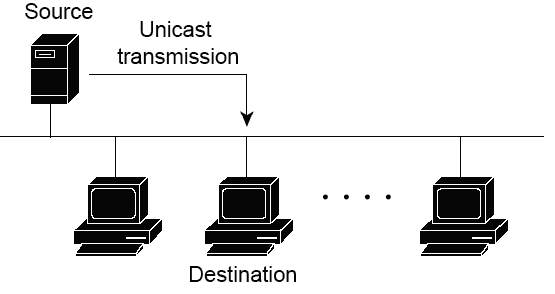
Тип передачи данных Unicast (индивидуальный) используется для обычной передачи данных от хоста к хосту. Способ Unicast работает в клиент-серверных и пиринговых (peer-to-peer, от равного к равному) сетях.
В unicast пакетах в качестве IP адреса назначения используется конкретный IP адрес устройства, для которого этот пакет предназначен. IP адрес конкретного устройства состоит из порции адреса сети (в которой находится это устройство) и порции адреса хоста (порции, определяющей это конкретное устойчиво в его сети). Это все приводит к возможности маршрутизации unicast пакетов по всей сети.
Multicast и broadcast пакеты, в отличие от unicast пакетов, имеют свои собственные специальные (зарезервированные) IP адреса для использования их в заголовке пакетов в качестве пункта назначения. Из-за этого, broadcast пакеты в основном ограничены пределами локальной сети. Multicast трафик также может быть ограничен границами локальной сети, но с другой стороны также может и маршрутизироваться между сетями.
В IP сетях unicast адрес является адресом, то есть адресом конечного устройства (например, компьютера). Для типа передачи данных unicast, адреса хостов назначаются двум конечным устройствам и используются (эти адреса) как IP адрес источника и IP адрес получателя.
В течение процесса инкапсуляции передающий хост размещает свой IP адрес в заголовок unicast пакета в виде адреса источника, а ИП адрес принимающего хоста размещается в заголовке в виде адреса получателя. Используя эти два IP адреса, пакеты unicast могут передаваться через всю сеть (т.е. через все подсети).
Multicast
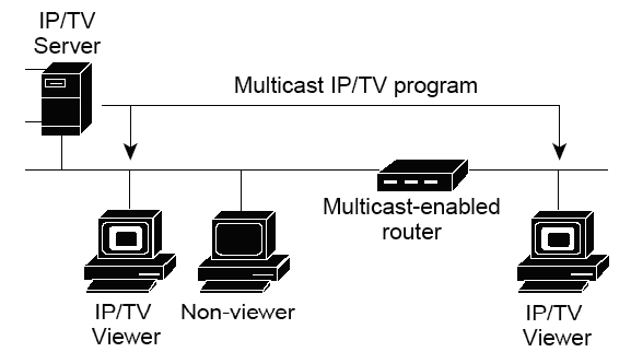
Тип передачи multicast разрабатывался для сбережения пропускной способности в IP сетях. Такой тип уменьшает трафик, позволяя хостам отправить один пакет выбранной группе хостов. Для достижения нескольких хостов назначения используя передачу данных unicast, хосту источнику было бы необходимо отправить каждому хосту назначения один и тот же пакет. С типом передачи данных multicast, хост источник может отправить всего один пакет, который может достичь тысячи хостов получателей.
Примеры multicast передачи данных:
- видео и аудио рассылка
- обмен информацией о маршрутах, используемый в маршрутизируемых протоколах.
- распространение программного обеспечения
- ленты новостей
Multicast клиенты
Хосты, которые хотят получить определенные multicast данные, называются multicast клиентами. Multicast клиенты используют сервисы инициированные (начатые) клиентскими программами для рассылки multicast данных группам.
Каждая multicast группа представляет собой один multicast IP адрес назначения. Когда хост рассылает данные для multicast группы, хост помещает multicast IP адрес в заголовок пакета (в раздел пункта назначения).
Для multicast групп выделен специальный блок IP адресов, от 224.0.0.0 до 239.255.255.255.
Broadcast
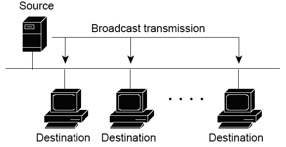
Из-за того, что тип передачи broadcast используется для отправки пакетов ко всем хостам в сети, пакеты использую специальный broadcast IP адрес. Когда хост получает пакет, в заголовке которого в качестве адреса получателя указан broadcast адрес, он обрабатывает пакет так, как будто это unicast пакет.
Когда хосту необходимо передать какую-то информацию всем хостам в сети используется способ передачи данных broadcast. Еще когда адрес специальных сервисов (служб) или устройств заранее неизвестен, то для обнаружения также используется broadcast (широковещание).
Примеры, когда используется broadcast передача данных:
- создание карты принадлежности адресов верхнего уровня к нижним (например, какой IP адрес на конкретном устройстве со своим MAC адресом)
- запрос адреса (в качестве примера можно взять протокол ARP)
- протоколы маршрутизации обмениваются информацией о маршрутах (RIP, EIGRP, OSPF)
Когда хосту нужна информация, он отправляет запрос на широковещательный адрес. Все остальные хосты в сети получат и обработают этот запрос. Один или несколько хостов вложат запрашиваемую информацию и ответят на запрос. В качестве типа передачи данных, отвечающие на запрос будут использовать unicast.
Подобным образом, когда хосту необходимо отправить информацию всем хостам в сети, он создаёт широковещательный пакет с его информацией и передаёт его в сеть.
В отличие от unicast передачи, где пакеты могут быть маршрутизированы через всю сеть, broadcast пакеты, как правило, ограничиваются локальной сетью. Это ограничение зависит от настройки маршрутизатора, который ограничивает сеть и следит за типом широковещания (broadcast).
Существует два типа broadcast передачи данных: направленное широковещание и ограниченное широковещание.
NAT, Port Forwarding and DMZ
NAT (Network Address Translation)
NAT (Network Address Translation) – трансляция (подмена) сетевых адресов. Эта технология широко используется. Позволяет с одной стороны, противостоять нехватке IPv4 адресов, а с другой – повысить защищённость сети.
NAT (Network Address Translation) - это такой механизм, который позволяет роутеру определять какие сервисы находятся за роутером и должны быть доступны из интернета, чтобы пользователи оттуда могли этими сервисами пользоваться (определение из вики я брать не стал, т.к. оно заумное и не всем понятное).
NAT присутствует во всех роутерах и серверных операционках в том или ином виде. В роутерах это обычно называется port forwarding, в линуксах iptables, на виндовых серверах - в специальной оснастке. А теперь давайте поговорим о различных типах NAT.
Трансляция сетевых адресов (NAT) используется многими сервис провайдерами и частными пользователями для решения проблемы нехватки реальных IP-адресов и обеспечения безопасности локальных сетей подключенных к Интернету. Например. Предприятие может иметь выделенный диапазон реальных IP-адресов, но гораздо большее количество компьютеров имеющих локальные IP-адреса которым необходим доступ в Интернет. Для решения этой проблемы используется технология трансляции адресов, которая позволяет компьютерам локальной сети взаимодействовать с сетью Интернет, используя всего один внешний реальный IP-адрес. NAT решает эту проблему с помощью подмены локального IP-адреса на наружный общедоступный адрес. Заменяя внутренний IP-адрес и порт на внешний IP-адрес и порт, NAT сохраняет таблицу соответствия, затем при получении ответного пакета производится обратное преобразование.
К локальным IP-адресам относятся следующие диапазоны адресов: 10.ххх.ххх.ххх, 192.168.ххх.ххх, 172.16.ххх.ххх - 172.32.ххх.ххх.
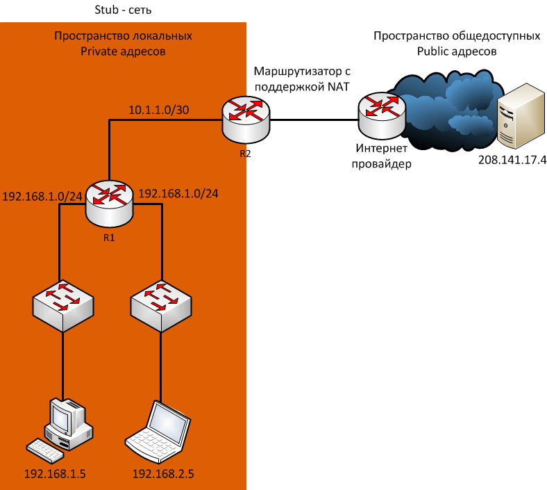
Сети обычно проектируются с использованием частных IP адресов. Это адреса 10.0.0.0/8, 172.16.0.0/12 и 192.168.0.0/16. Эти частные адреса используются внутри организации или площадки, чтобы позволить устройствам общаться локально, и они не маршрутизируются в интернете. Чтобы позволить устройству с приватным IPv4-адресом обращаться к устройствам и ресурсам за пределами локальной сети, приватный адрес сначала должен быть переведен на общедоступный публичный адрес.
И вот как раз NAT переводит приватные адреса, в общедоступные. Это позволяет устройству с частным адресом IPv4 обращаться к ресурсам за пределами его частной сети. NAT в сочетании с частными адресами IPv4 оказался полезным методом сохранения общедоступных IPv4-адресов. Один общедоступный IPv4-адрес может быть использован сотнями, даже тысячами устройств, каждый из которых имеет частный IPv4-адрес. NAT имеет дополнительное преимущество, заключающееся в добавлении степени конфиденциальности и безопасности в сеть, поскольку он скрывает внутренние IPv4-адреса из внешних сетей.
Маршрутизаторы с поддержкой NAT могут быть настроены с одним или несколькими действительными общедоступными IPv4-адресами. Эти общедоступные адреса называются пулом NAT. Когда устройство из внутренней сети отправляет трафик из сети наружу, то маршрутизатор с поддержкой NAT переводит внутренний IPv4-адрес устройства на общедоступный адрес из пула NAT. Для внешних устройств весь трафик, входящий и выходящий из сети, выглядит имеющим общедоступный IPv4 адрес.
Маршрутизатор NAT обычно работает на границе Stub-сети. Stub-сеть – это тупиковая сеть, которая имеет одно соединение с соседней сетью, один вход и выход из сети.
DMZ vs Port Forwarding
DMZ (Demilitarized Zone) and Port Forwarding are two terms often used when dealing with internet security. Although they are both used in security, the main difference between the two is how they improve the security. A DMZ is a small part of the network that is openly accessible to the public network or the internet. In comparison, port forwarding is the technique to still have the certain functionalities available even with a firewall in place. Port forwarding doesn’t really add security per se but it does so indirectly by eliminating the reason for not putting up a firewall.
A DMZ doesn’t seem to make sense when you consider that it exposes a part of the network to intrusions from the public network. The main reason behind the DMZ is the protection of the rest of the network. Parts of the network that should be accessible to the public create a security risk since the possibility of the entire network being compromised once that part is. Relocating these services to the DMZ allows the admin to implement tighter security on the rest of the network. Additional firewalls are often put-up between the DMZ and the internal network.
Port forwarding is not really essential and you can still use the internet without it. The problem arises when you want an external application to have the ability to connect to certain services on your machine. It would automatically be blocked by the firewall since the connection was not initiated from within. Once port forwarding is implemented, the router would forward the requests received on a certain port to a specific machine on the network, which services the request. An example where port forwarding is applicable is if you plan to run a web, email, or file server on your computer.
Port forwarding is very common and many people have it in place even if they are not running servers. Some applications, like peer to peer file sharing applications, need port forwarding to function at optimum speeds. In comparison, DMZs are not as common and is used mainly by large companies or institutions that offer web services. It serves their need to separate the public and private parts of their networks.
Summary
- A DMZ is a location while port forwarding is a technique
- Port forwarding is used by almost all while DMZs are only used by large institutions
Using network tools (tcpdump, nmap, WireShark)
tcpdump
Очень часто для поиска проблем в работе сети используются анализаторы сетевого трафика. tcpdump является одним из представителей данного класса программ, она позволяет прослушать (отобразить/сохранить) и проанализировать работу сети на уровне передаваемых сетевых пакетов, фреймов и др. единиц передачи сетевого трафика. В зависимости от конфигурации сети, tcpdump может прослушивать не только пакеты, предназначенные данному MAC-адресу, но и широковещательные пакеты. Прослушивание перехват сетевых пакетов основан на "беспорядочном" (promiscuous) режиме работы сетевого адаптера.
В зависимости от используемого сетевого оборудования для соединения компьютеров в сети Ethernet существуют следующие возможности прослушивания трафика:
- В сети на основе концентраторов весь трафик с концентратора хаба доступен любому сетевому хосту.
- В сетях на основе коммутаторов (свичей) сетевому хосту доступен только ее трафик, а также весь широковещательный трафик данного сегмента.
- Некоторые управляемые коммутаторы имеют функцию копирования трафика данного порта на порт мониторинга ("зеркалирование",мониторинг порта).
- При использовании специальных средств (ответвителей), включаемых в разрыв сетевого подключения и передающих трафик подключения на отдельный порт возможно прослушивание соответствующего порта.
- "Трюк" с концентратором — порт коммутатора, трафик которого необходимо прослушать, включают через концентратор, подключив к концентратору также узел-монитор (при этом в большинстве случаев уменьшается производительность сетевого подключения).
Итак, утилита tcpdump входит в большинство дистрибутивов Unix и позволяет перехватывать и отображать/сохранять в файл сетевой трафик. Утилита использует библиотеку libpcap. Для Windows тоже существует порт. Для работы утилиты ее необходимо установить.
debian:~# tcpdump -i eth0 host 10.0.0.1
nmap
Nmap («Network Mapper») — это инструмент с открытым исходным кодом для исследования сети и аудита безопасности. Он был разработан для быстрого сканирования больших сетей. Nmap использует необработанные IP-пакеты, чтобы определить, какие хосты доступны в сети, какие сервисы (имя и версия приложения) предлагают эти хосты, в каких операционных системах (и версиях ОС) они работают, какой тип фильтров/брандмауэров пакетов находятся в использовании и десятки других характеристик. Хотя Nmap обычно используется для аудита безопасности, многие системные и сетевые администраторы считают его полезным и для рутинных задач, таких как инвентаризация сети, управление расписаниями обновления служб и мониторинг времени работы хоста или службы.
Nmap был написан Гордоном Лионом. Данный инструмент запросто способен ответить на следующие вопросы:
- Какие компьютеры работают в локальной сети?
- Какие IP-адреса работают в локальной сети?
- Какая операционная система на вашей целевой машине?
- Какие порты открыты на машине, которую вы только что отсканировали?
- Заражена ли система вредоносным ПО или вирусом?
- Поиск неавторизованных серверов или сетевых услуг в вашей сети.
- Поиск и удаление компьютеров, которые не соответствуют минимальному уровню безопасности.
Например, Сканирование одного хоста или IP-адреса (IPv4):
### Scan a single ip address ###
nmap 192.168.1.1

## Scan a host name ###
nmap server1.sedicomm.com

## Scan a host name with more info###
nmap -v server1.sedicomm.com
Wireshark
Даже поверхностное знание программы Wireshark и её фильтров на порядок сэкономит время при устранении проблем сетевого или прикладного уровня. Wireshark полезен для многих задач в работе сетевого инженера, специалиста по безопасности или системного администратора. Вот несколько примеров использования:
Устранение неполадок сетевого подключения
- Визуальное отображение потери пакетов
- Анализ ретрансляции TCP
- График по пакетам с большой задержкой ответа
Исследование сессий прикладного уровня (даже при шифровании с помощью SSL/TLS, см. ниже)
- Полный просмотр HTTP-сессий, включая все заголовки и данные для запросов и ответов
- Просмотр сеансов Telnet, просмотр паролей, введённых команд и ответов
- Просмотр трафика SMTP и POP3, чтение писем
Устранение неполадок DHCP с данными на уровне пакетов
- Изучение трансляций широковещательного DHCP
- Второй шаг обмена DHCP (DHCP Offer) с адресом и параметрами
- Клиентский запрос по предложенному адресу
- Ack от сервера, подтверждающего запрос
Извлечение файлов из сессий HTTP
- Экспорт объектов из HTTP, таких как JavaScript, изображения или даже исполняемые файлы
Извлечение файлов из сессий SMB
- Аналогично опции экспорта HTTP, но извлечение файлов, передаваемых по SMB, протоколу общего доступа к файлам в Windows
Secure connections with SSL/TLS (basic understanding)
- SSL — Secure Socket Layer
- TLS — Transport Layer Security
SSL — Secure Socket Layer, уровень защищенных сокетов. TLS — Transport Layer Security, безопасность транспортного уровня. SSL является более ранней системой, TLS появился позднее и он основан на спецификации SSL 3.0, разработанной компанией Netscape Communications. Тем не менее, задача у этих протоколов одна — обеспечение защищенной передачи данных между двумя компьютерами в сети Интернет. Такую передачу используют для различных сайтов, для электронной почты, для обмена сообщениями и много еще для чего. В принципе, можно передавать любую информацию таким образом, об этом чуть ниже.
Безопасная передача обеспечивается при помощи аутентификации и шифрования передаваемой информации. По сути эти протоколы, TLS и SSL, работают одинаково, принципиальных различий нет. TLS, можно сказать, является преемником SSL, хотя они и могут использоваться одновременно, причем даже на одном и том же сервере. Такая поддержка необходима для того, чтобы обеспечить работу как с новыми клиентами (устройствами и браузерами), так и с устаревшими, которые TLS не поддерживают. Последовательность возникновения этих протоколов выглядит вот так:
- SSL 1.0 — никогда не публиковался
- SSL 2.0 — февраль 1995 года
- SSL 3.0 — 1996 год
- TLS 1.0 — январь 1999 года
- TLS 1.1 — апрель 2006 года
- TLS 1.2 — август 2008 года
SSL certificate
Сертификат открытого ключа (public key certificate, digital certificate или identity certificate, а так же сертификат, сертификат ключа подписи, сертификат ключа проверки электронной подписи) — электронный документ, подтверждающий принадлежность публичного ключа его владельцу.
Сертификат выдаётся и подписывается Certificate Authorities, которые подписывают выданные сертификаты своей цифровой подписью, подтверждая, что владелец сертификата (и публичного ключа, включённого в этот сертификат) был проверен
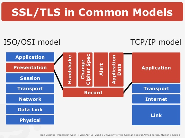
Принцип работы SSL и TLS
Принцип работы SSL и TLS, как я уже сказал, один и тот же. Поверх протокола TCP/IP устанавливается зашифрованный канал, внутри которого передаются данные по прикладному протоколу — HTTP, FTP, и так далее. Вот как это можно представить графически:

Прикладной протокол «заворачивается» в TLS/SSL, а тот в свою очередь в TCP/IP. По сути данные по прикладному протоколу передаются по TCP/IP, но они зашифрованы. И расшифровать передаваемые данные может только та машина, которая установила соединения. Для всех остальных, кто получит передаваемые пакеты, эта информация будет бессмысленной, если они не смогут ее расшифровать.
Установка соединения обеспечивается в несколько этапов:
Клиент устанавливает соединение с сервером и запрашивает защищенное подключение. Это может обеспечиваться либо установлением соединения на порт, который изначально предназначен для работы с SSL/TLS, например, 443, либо дополнительным запросом клиентом установки защищенного соединения после установки обычного.
При установке соединения клиент предоставляет список алгоритмов шифрования, которые он «знает». Сервер сверяет полученный список со списком алгоритмов, которые «знает» сам сервер, и выбирает наиболее надежный алгоритм, после чего сообщает клиенту, какой алгоритм использовать
Сервер отправляет клиенту свой цифровой сертификат, подписанный удостоверяющим центром, и открытый ключ сервера.
Клиент может связаться с сервером доверенного центра сертификации, который подписал сертификат сервера, и проверить, валиден ли сертификат сервера. Но может и не связываться. В операционной системе обычно уже установлены корневые сертификаты центров сертификации, с которыми сверяют подписи серверных сертификатов, например, браузеры.
Генерируется сеансовый ключ для защищенного соединения. Это делается следующим образом: — Клиент генерирует случайную цифровую последовательность — Клиент шифрует ее открытым ключом сервера и посылает результат на сервер — Сервер расшифровывает полученную последовательность при помощи закрытого ключа Учитывая, что алгоритм шифрования является асимметричным, расшифровать последовательность может только сервер. При использовании асимметричного шифрования используется два ключа — приватный и публичный. Публичным отправляемое сообщение шифруется, а приватным расшифровывается. Расшифровать сообщение, имея публичный, ключ нельзя.
Таким образом устанавливается зашифрованное соединение. Данные, передаваемые по нему, шифруются и расшифровываются до тех пор, пока соединение не будет разорвано.
При использовании SSL/TLS одним из основных методов является метод MITM (Man In The Middle), «человек посередине». Этот метод основывается на использовании серверного сертификата и ключа на каком-то узле, который будет прослушивать трафик и расшифровывать информацию, которой обмениваются сервер и клиент. Для организации прослушивания можно использовать, например, программу sslsniff. Поэтому корневой сертификат и ключ обычно желательно хранить на машине, которая не подключена к сети, для подписания приносить запросы на подпись на флэшке, подписывать и так же уносить. И, естественно, делать резервные копии.
В общих чертах именно так и используются цифровые сертификаты и протоколы TLS и SSL. Если есть вопросы/дополнения, пишите в комментарии.
Симметричное шифрование
Процесс, при котором шифрование и дешифрование выполняется с помощью одного и того же ключа, которым стороны должны обменяться до начала шифрования.
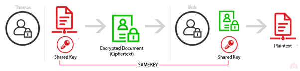
Основной проблем симметричного шифрования как раз явлется сам факт того, что данные должны быть зашифрованы одним и тем же ключём.
Если этот ключ будет перехвачен злоумышленником — он получит возможность расшировать все данные, зашифрованные этим ключём.
Именно поэтому передача такого ключа должна осуществляться по уже зашированному соединению.
Преимущества
- быстрое, низкое потребление ресурсов системы
- простые операции
- безопасно
Недостатки
- один ключ для шифрования/дешифрования
- передача ключа должна быть выполнена по уже защищённому соединению
- нет возможности авторизации пользователей
Ассиметричное шифрование
Asymmetric encryption (также Public Key Cryptography — криптография по открытому ключу) использует пары ключей — публичный и приватный. Эти ключи связаны друг с другом таким образом, что данные, зашифрованные с помощью одного ключа (как правило публичного) могут быть расшифрованы другим (приватным).
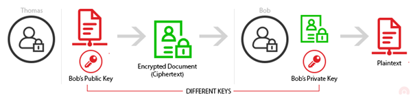
Асссиметричное шифрование так же может применяться для авторизации отправителя: если Боб подписывает и шифрует сообщение, используя свой приватный ключ, то любой, у кого есть публичная часть ключа и кто смог расшифровать такое сообщение может быть уверен, что его зашифровал и отправил только Боб (при условии, что Боб не слил свой приватный ключ в Github…).
Преимущества
- простая передача ключа
- аутентификация пользователей
- проверка целостности
Недостатки
- медлененее, чем симметричное шифрование
- потребляет больше ресурсов
VPN and tunnels
Virtual Private Networks (VPNs) have become one of the cornerstones of secure communications over the internet. However, there has been a lot of confusion around what VPNs can and cannot do. That confusion has led many technologists to choose a VPN solution that may not be well suited for their particular environment. However, that confusion can be quickly eliminated with a little bit of education, especially when it comes to VPN Tunnels. One major concern around VPNs is the issue of how secure they are. In other words, can VPNs fully protect the privacy and content of the data being transmitted?
VPNs are a connection method used to add security and privacy to data transmitted between two systems. VPNs encapsulate data and encrypt the data using an algorithm contained within the transmission protocol. VPN traffic is encrypted and decrypted at the transmission and receiving ends of the connection.
Today’s VPNs primarily use one of the three major protocols, each of which has its advantages and disadvantages:
PPTP is one of the oldest protocols and came into existence back in the days of Windows 95. PPTP proves to be one of the easiest protocols to deploy and is natively supported by most major operating systems. However, PPTP uses what is known as GRE (Generic Routing Encapsulation), which has been found to have vulnerabilities. In other words, PPTP may be easy to set up, but it’s security is the weakest of the common VPN protocols.
VPNs can also be set up using L2TP/IPsec protocols, which proves to have much stronger encryption than PPTP. L2TP/IPsec are actually a combination of two secure protocols that work in concert to establish a secure connection and then encrypt the traffic. L2TP/IPsec is a little more difficult to setup than PPTP, and can add some latency to a connection.
Another protocol that is gaining favor is OpenVPN, which is based upon SSL (Secure Sockets Layer) for it’s encryption protocol. OpenVPN is open source and freely available. However, OpenVPN requires a certificate, which means users of the protocol may have to purchase a certificate from a certificate authority.
Regardless of which protocol you choose, VPNs need to “Tunnel” the data between the two devices. So, in essence, a VPN Tunnel is the actual connection mechanism, it is the data link that surrounds the encrypted traffic and establishes a secure connection.
VPNs have become an established method to ensure privacy, protect data, and are becoming very popular among internet users. Many organizations are now offering VPNs for private use, with the primary goal of protecting Internet users’ privacy. The way these services work is by offering a VPN host, which the end user connects to via a piece of client software on their device. All of the traffic between the device and the host is encrypted and protected from snooping. In other words, ISPs, broadband service providers, and any other entity that exists between the client and the host can not see the data that is in the VPN Tunnel, which preserves privacy.
While personal privacy is naturally a major concern, businesses and organizations should also be focused on privacy and protecting data. Organizations that have multiple offices or remote workers should also be encrypting and protecting data. Today’s businesses are transmitting proprietary information, intellectual property, and perhaps even customer data across the internet. Many businesses are also bound by compliance regulations, directing those businesses to protect customer privacy, as well as other data.
However, VPNs may not be the best solution for all businesses. Simply put, VPN Tunnels are still subject to man in the middle attacks and the interception of data. While encryption may be very hard to break, it is not completely impossible. What’s more, in the not too distant future, Quantum Computers may be able to crack any of the existing encryption methodologies in a matter of minutes. That means those concerned with keeping data secure will have to look beyond the VPN Tunnel.
Arguably, the best way to prevent data from being intercepted over the internet is not to use the internet at all. However, for the majority of organizations that is simply not feasible. The internet has become the connective tissue between businesses sites and is a necessity for transmitting email, data files, and even web traffic.
However, enterprises can still secure their data communications and encrypt critical data without the risk of interception by using SD-WAN technology. A Software Defined Wide Area Network can be used to establish connection privacy between sites. SD-WANs bring forth concepts such as VLANs (Virtual Local Area Networks) that can communicate across an SD-WAN platform to establish secure connections. What’s more, SD-WANs can incorporate a full security stack, meaning that all traffic is examined for malware, intrusion attempts, and any other malicious activity. SD-WANs also prove easier to manage than multiple VPN clients and servers and offer the flexibility to adapt to changing business needs.
Basic understanding of IP routing
IP routing is a process of transferring data from one network to another as IP packets. By default, hosts of different networks cannot communicate with each other. If two hosts located in different IP networks want to communicate with each other, they use IP routing.
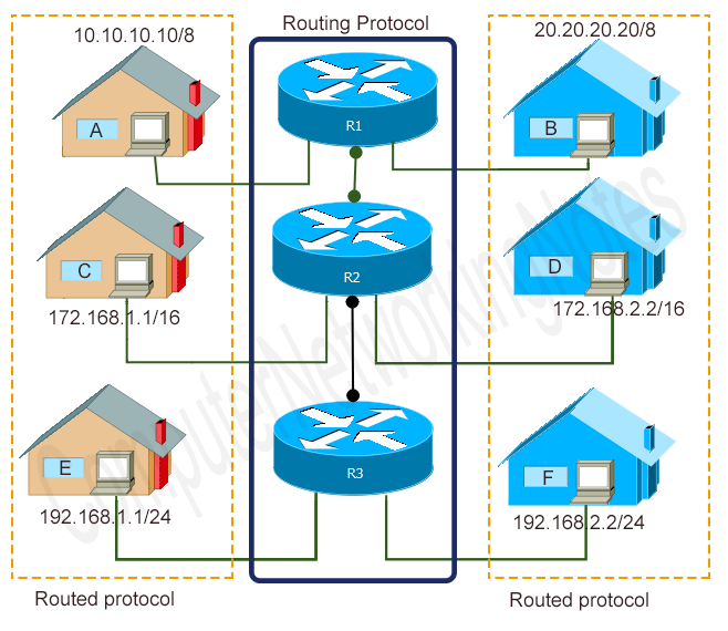
Routers provide IP routing. A router is a specialized device that connects different IP networks. Let’s take a simple example. Suppose two IP hosts; 10.10.10.10/8 and 20.20.20.20/8 want to communicate. Since they both belong to the different IP networks, they need a router to communicate.
The following image shows this example.

The complete IP routing process relies on two types of protocols; routed protocols and routing protocols. Before we understand how the IP routing works, let’s understand the differences between both types of protocols.
Routing protocols v/s Routed or Routable protocols
A routed protocol is used to encapsulate the data that is exchanged between the source host and the destination host. In IP routing, the IP protocol is used as the routed protocol.
By using the IP protocol, a source host packs data pieces and adds the source address and the destination address on each data piece. A data piece with both addresses (source and destination) is known as the IP packet.
Any router that works on a path that connects the source host to the destination host uses both (source and destination) addresses to find out where the packet came from and where it will go.
Routing protocols
Routers use a routing protocol for the following purposes.
To figure out all available paths of the network. A router stores these paths in a table known as the routing table.
To select the best and fastest path to get a destination host. When a router receives an IP packet, the router checks its routing table and compares all available paths to get the destination network of the received IP packet and selects the fastest path from all available paths.
RIP, IGRP, EIGRP, and OSPF are examples of routing protocols.
How does IP routing work?
The process of IP routing begins when a host creates a data packet for a host that is located in another network and ends when that destination host receives the packet. To understand this process in detail, let’s take a simple example.
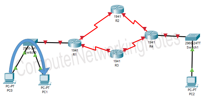
The following image shows the layout of a network. In this network, PC0 and PC1 are connected to PC2 via four routers; R1, R2, R3, and R4.
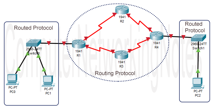
Suppose, an application running on PC0 wants to send some data to PC1. The application calls the IP protocol of PC0 and hands that data over to the IP protocol. The IP protocol packs data into packets and adds source and destination addresses to each packet.
After this, the IP protocol uses another protocol known as ARP protocol to figure out whether the destination address (PC1) is located in the local network (the same IP network) or is located in the remote network (another IP network).
If the destination address is located in the same IP (local) network, the IP protocol sends packets directly to the destination host.
The entire routing process is controlled by the routed (IP) protocols of PC0 and PC1.
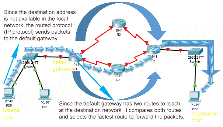
Now suppose that the same application wants to send data to PC2. The same process is repeated until the packet forwarding decision is made by the IP protocol. This time, since the destination host (PC2) is located in the remote network (another IP network), the IP protocol sends packets to the default gateway.
A default gateway is an interface of a router that connects the local network with the remote network. By default, an IP protocol forwards all packets to the default gateway except the packets that belong to the local IP network.
The default gateway router not only keeps records of all remote networks but also keeps records of all available paths for each remote network. A router maintains these records in the routing table. A typical routing table entry consists of two pieces; the network address and the interface on which that network is available.
When a router receives a packet on any of its interfaces, it reads the destination network of that packet and finds that network in the routing table. If the routing table contains a record for that network, the router uses that record to forward the packet. If the routing table doesn’t contain a record for that network, the router discards that packet.
If multiple paths to a remote network exist, the router chooses the fastest path from them.
In our example, the default gateway router R1 has two paths to reach to PC2's network. When it receives packets for PC2 from PC0, it compares both paths and chooses the fastest path to forward packets.
PC2 receives packets from its default gateway router R4. The entire routing process is controlled by both types of protocols; routed and routing protocols.